


Modeling Complexities Of Natural Fracturing Key In Gas Shales
By William Dershowitz and Thomas W. Doe
REDMOND, WA.–Safe, efficient, and profitable development of shale natural gas resources depends on achieving a clear understanding of the role of natural fractures in shale gas production.
Natural fracturing is critical to enhancing stimulation treatment design and optimizing well performance. Although every shale formation is somewhat different, there can be significant variations in natural fracture systems from one location to another within a given play area, with equally significant differences in production rates from one well to another.
Reservoir development is impacted by natural fractures in three ways. First, natural fractures are planes of weakness that may control hydraulic fracture propagation. Second, high pressures from the hydraulic frac treatment may cause slip on natural fractures that increases their conductivity. Third, natural fractures that were conductive prior to stimulation may affect the shape and extent of a well’s drainage volume.
There are three classes of shale gas reservoirs, and the strategy for developing each class of reservoir can be dramatically different. The reservoir classifications are based on the degree of natural fracturing and how gas is stored within the shale:
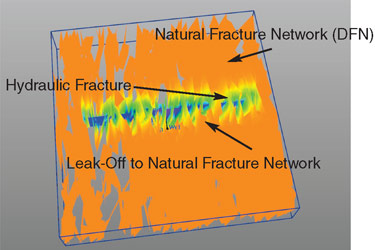
FIGURE 1
Leak-Off from Hydraulic Fracture To Natural Fracture Network
- Type A: Hydraulic fracture propagation provides the only flow pathway to the well.
- Type B: Hydraulic fracture propagation provides the primary flow pathway to the well, but is supplemented by natural fractures that are critically stressed by frac fluids (especially rough fractures).
- Type C: Frac fluid “leak off” to natural fractures is extensive (Figure 1), and production is through a combined network defined by the hydraulic fractures and natural fractures (or perhaps by the natural fractures alone).
FIGURE 2
Type A Gas Shale Reservoir (Flow from Hydraulic Fractures only)
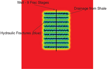
While a play may include all three types of reservoirs, it is essential to identify which reservoir type is dominant. For Type A reservoirs (Figure 2), where the only flow paths are hydraulically induced fractures, gas storage is exclusively within the shale rock matrix. For Type B (Figure 3) and C (Figure 4) reservoirs, gas can be stored in some combination of shale rock matrix and natural fractures. The reservoir type has a profound influence on the reservoir recovery factor, initial production, and the decline curve of production over time.
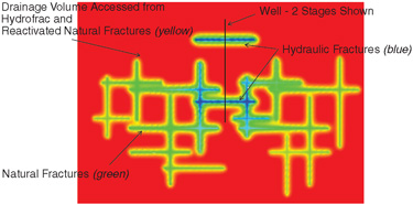
FIGURE 3
Type B Gas Shale Reservoir (Flow from Hydraulic and Natural Fractures)
This type of fine-tuning of the choice of approaches works well in shale gas plays, because in many cases, these developments have the advantage that comes from having plentiful high-quality data characterizing reservoirs, even in early stages of development.
Fracture image logs provide insights into the natural fracture pattern, production logs and gas returns support understanding of how gas is delivered to the well bore both before and after fracturing, and 3-D seismic provides a clear picture of stratigraphy and faulting. Microseismic and seismic energy monitoring provides a 3-D visualization of hydraulic fractures and reactivated natural fractures.
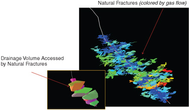
FIGURE 4
Type C Gas Shale Reservoir (Reactivated and Connected Natural Fractures Dominate Production)
Despite this wealth of information, many operators still develop shale gas fields using empirical approaches, ignoring the natural fracture patterns and spending tens of millions of dollars on inefficient or even counterproductive hydraulic fracturing strategies. Operators tend to develop shale gas as a “resource play,” as if the production from each well was equivalent, while in fact, some wells in a reservoir can produce 5, 10 or even 20 times more gas than average wells.
Fracture network models provide a means of quantifying hydraulic properties from measured fracture data. Depending on the scale of fracturing, fracture network models can be used to estimate hydraulic parameters for reservoir simulation and production performance. Discrete fracture network (DFN) technology leverages the wealth of available data to understand both the storage of gas in the shale reservoir, and the delivery of gas through fractures–both natural and hydraulically induced.
DFN Analysis
Figure 5 shows the impact of key natural fracture properties on the stimulated reservoir volume after hydraulic fracturing. The DFN approach for natural and hydraulic fractures provides analyses and workflows that help leverage the wealth of data collected for shale gas reservoirs, and uses that information to determine the type of shale reservoir and the best strategy for its development.
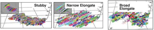
FIGURE 5
Impact of Natural Fracture Properties on Stimulated Reservoir Volume
In terms of natural fracture geometry and properties, fracture image logs provide information on electrically conductive and resistive natural fractures and bedding at well control. Image log technology is increasingly being used on horizontal wells to provide improved insights into subvertical fracture sets, which can dominate shale gas plays.
New drill bit fracture imaging technologies provide significant improvements to imaging, particularly for the horizontal wells that are used for shale gas development. The DFN approach utilizes geologic, geophysical and geomechanical information to extrapolate the natural fracture pattern beyond well control to the entire reservoir.
Where controlling the vertical extent of fractures is a concern, it is essential to start fracture image logging substantially above the targeted reservoir horizon. It has been observed that in some reservoirs, only electrically conductive (“open” and “partially open”) fractures are important, while in other reservoirs, closed and healed fractures, and bedding planes can provide a significant influence on shale gas production.
Stratigraphic surfaces and faulting can be derived from 2-D seismic data, but are now routinely supplemented by 3-D seismic interpretations. Seismic processing technologies such as amplitude-variation-with-offset have the additional advantage of characterizing liquids, which has been problematic.
While it is widely recognized that in situ stress plays an essential role in controlling hydraulic fracturing, the role of local in situ stress variability in fractured rocks also can be very important. Each hydraulic fracture provides a stress shadow–as indeed do many natural fractures. Also, fault blocks can create local in situ stress conditions that are significantly different from regional conditions.
The propagation of hydraulic fractures, and their interaction with natural fractures, is tightly dependent on in situ stress conditions. Consequently, the derivation of in situ stress and its spatial variability is a key portion of the discrete fracture network workflow. In some cases, in situ stress can be derived from drilling-induced tension fractures and bore hole breakouts seen in fracture image logs, while in other cases, it is best back-calculated from frac records and microseismic monitoring, or estimated from calibrated geomechanical simulations.
Rock mass and fracture geomechanical properties are keys to understanding fracture propagation, and especially, vertical controls on propagation beyond reservoir horizons. Rock mass elastic modulus and strength properties can be estimated from wireline and seismic, but are more accurate when supplemented by core and sidewall core testing. In particular, fracture toughness and rock mass modulus (compressibility) are very important controls on the hydraulic fracturing process, and should be estimated as part of any DFN analysis workflow.
Reservoir pressures are also crucial. Hydraulic fracture propagation is controlled by “effective stress,” which is defined by the total stress minus the reservoir pressure. As a result, accurate evaluation of fracture propagation also requires accurate estimates of reservoir pressure. This is particularly important where the reservoir pressure is a significant fraction of the minimum stress, which can occur frequently, particularly in overpressured reservoirs.
While hydraulic fractures generally are assumed to propagate in tension, the combination of pre-existing natural fractures and high reservoir pressures can result in hydraulic fractures formed primarily as a coalescence of natural fractures affected by frac fluid pressures. This process occurs as a combination of tensional and shear propagation.
Geomechanical Simulation
Discrete fracture network geomechanical simulation has the advantage that it starts from a realistic model of the natural fractures, so that the natural fracture/hydraulic fracture interaction can be modeled explicitly. Geomechanical modeling requires the ability to model both the deformation of the rock mass (allowing fractures to accept frac fluids and proppant), and the fracture propagation process itself.
Rock mass deformation is a combination of fracture deformation and the deformation of the rock matrix to accommodate frac fluids penetrating natural and induced fractures. It has been demonstrated clearly that rock mass effective deformability is a combination of rock mass deformability (generally characterized by shear modulus and Poisson’s ratio) and fracture deformability (generally characterized as fracture shear and normal stiffness). Procedures exist for estimating rock mass deformability based on the types of fracture and rock characterization activities that are typically carried out for shale reservoirs, as well as for estimating where detailed characterization has not yet been carried out.
The derived rock mass deformability parameters then can be used in geomechanical simulations. When fractures and bedding are considered, rock mass deformation in shale is generally anisotropic, which needs to be considered carefully in frac job design and monitoring.
Two approaches are available for geomechanical simulation of hydraulic fracture propagation and interaction with natural fractures within a DFN. The fully coupled, flow/geomechanical approach requires the use of a finite element code that can simulate both fracture and rock mass deformation, and also simulate frac fluid and proppant flow and fracture propagation.
The distinct element method meets all these requirements, particularly when integrated with a conventional finite element analysis approach such as Rockfield Software Ltd.’s ELFEN™ code for numerical modeling. The advantage of the code in fully coupled 2-D or 3-D geomechanical simulation is somewhat balanced by the limitations of computation time, which limits the number of natural fractures that can be considered. The simpler alternative, a fully 3-D DFN approach, uses a less rigorous analysis, constrained by mass balance and simple elastic models of fracture growth and inflation (for example, the PKN model).
Answering Key Questions
Discrete fracture network analyses synthesize available reservoir geologic, frac and production data to answer key reservoir development questions, such as:
- What tributary drainage volume is drained by any given hydraulic fracture or series of fractures?
- What depth of rock matrix is effectively drained to hydraulic fractures?
- How are fracture heights controlled both to improve production efficiency and to minimize environmental risk?
- What is the most effective frac stage spacing and length to maximize production?
- What portions of a field are likely to be most productive?
- Is water production a risk, and if so, how can it be mitigated?
This type of analysis can help improve production efficiencies and improve environmental safety in shale gas extraction.
WILLIAM DERSHOWITZ is the technical director of the FracMan Technology Group and a principal of Golder Associates Inc. in Redmond, Wa. He has pioneered natural fracture analysis for oil and gas reservoirs for more than 25 years, introducing FracMan, the first commercial discrete fracture network modeling software in 1987. Dershowitz received a Ph.D. in rock mechanics from the Massachusetts Institute of Technology in 1985. He serves as treasurer of the American Rock Mechanics Association, and serves on the advisory board of the “Rock Mechanics and Rock Engineering” journal.
THOMAS W. DOE is an authority on hydraulic fracturing, with more than 30 years of hydraulic fracturing experience on six continents. He is a principal of Golder Associates in Redmond, Wa., and a member of the FracMan Technology Group. Doe served on the U.S. National Committee for Rock Mechanics’ Committee on Fracture Characterization and Fluid Flow, and is the author of “Fractured Bedrock Field Methods and Analytical Tools,” a standard reference for fractured rock characterization. He holds a B.A. in geology from Pomona College, and a Ph.D. in geology and mining engineering from the University of Wisconsin-Madison.
For other great articles about exploration, drilling, completions and production, subscribe to The American Oil & Gas Reporter and bookmark www.aogr.com.

