


Drill String Design
Aluminum Pipe, Steerable Motors Improve Drilling Performance In Eagle Ford Horizontals
By Stéphane Menand, Jeffry K. Lehner, Nigel Evans, Aaron Palmer and Arthur Metcalfe
HOUSTON–High strength-to-weight aluminum alloy drill pipe is a powerful torque and drag reduction tool for horizontal and deviated wells. Aluminum drill pipe (ADP) enables achieving strength-to-weigh ratios equivalent to 160 ksi yield-strength steels and is typically 30-50 percent lighter than similarly sized steel drill pipe (SDP).
Penn Virginia Corp. tested ADP in complex and highly deviated well profiles on a four-well pad in the Eagle Ford Shale–the first such application of ADP in a horizontal shale play. A “mixed” drill string design was used in three of the four extended-reach wells to drill the curve and laterals sections with ADP, while drilling the vertical sections with standard SDP. The drill string for the other well consisted of only SDP.
All four wells were designed with 7,000-foot lateral sections and utilized steerable mud motors. The wells are spaced 15 feet apart at the surface, and the typical lateral separation was 400-600 feet. The wells drilled with the ADP string had significantly improved rates of penetration and reduced torque compared to the well drilled with the SDP-only string using the same bottom-hole assembly (BHA) and bit.
TABLE 1
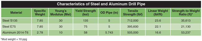
Given its light weight and strength-to-weight characteristics, ADP is well suited to long deviated or extended-reach wells, where reducing torque and drag loads is critical to drilling performance. The most common alloy used in manufacturing ADP has a maximum yield strength of 58,000 psi. While this is considerably lower than common steel pipe grades, the strength-to-weight ratio of ADP is equivalent to or better than steel pipe because of its lighter material density and greater buoyancy effect. ADP typically has a greater wall thickness than equivalent SDP, and is generally at least 40 percent lighter than equivalent-sized steel pipe.
Table 1 compares the mechanical properties of steel and aluminum grades in terms of density, Young’s modulus, yield and tensile strength, and the strength-to-weight ratio for 5-inch SDP and 5 7⁄8-inch ADP. The strength-to-weight ratio represents the ultimate length of a single size drill string that can be suspended without exceeding the yield strength of the material.
ADP’s high strength-to-weight ratio decreases torque and drag loads while maintaining resistance to axial, torsional and lateral loads. Since aluminum alloys are more flexible than steel, ADP buckles at a lower given compression than SDP. However, the increased flexibility is balanced by the fact that the lighter weight reduces contact side forces to minimize friction between the drill string and borehole. Minimizing friction decreases hook load and torque at the surface, and importantly, reduces compression while running an ADP string in the hole to potentially extend horizontal reach.
Extending Lateral Reach
The favorable results in the Eagle Ford test indicate that using ADP in association with a steerable mud motor could be an economically and technically viable alternative to rotary steerable systems. The principal advantage of using a rotary steerable system is the ability to control the direction of the well in the rotary mode, overcoming drag friction to extend the lateral section further into the target formation.
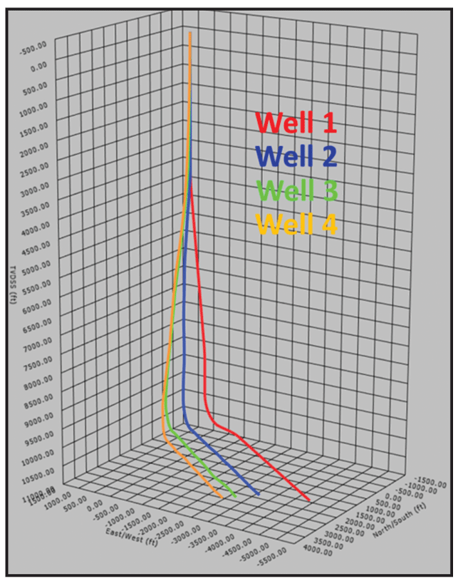
FIGURE 1
3-D View of Four Eagle Ford Wells
Horizontal drilling with a steerable mud motor consists of a sequence of sliding phases (generally 10-20 percent of the total footage drilled) and rotary phases (80-90 percent of the footage). Pipe rotation at surface is stopped during the sliding mode to adjust tool face orientation to steer the bit in a given direction, and weight is then applied on the mud motor-rotated bit.
In the slide mode, drag friction generates compression all along the drill string, with a risk of buckling and poor weight transfer to the bit. When a steerable mud motor is in slide mode, it creates a situation for maximum compression along the drill string, and the excessive friction limits the extent of the horizontal section. In the rotary mode, drill pipe rotation at surface resumes, overcoming the drag friction (rotary mode ROP can be 10 times greater than in sliding mode), but the direction of the well is not fully controlled.
Oscillation, where the drill pipe is rocked alternatively to the left and right at surface at low rotation speed to reduce axial drag, is one solution to limitations while drilling in the sliding mode with a steerable mud motor. Instead of generating axial drag while sliding, friction occurs along the tangential direction (torque) because of the oscillation from the surface on a given portion along the drill string (the drill string is twisted). This technique has proven effective, leading to better weight transfer to the bit and higher sliding mode ROP.
Another option is an axial oscillation tool, which generates pressure pulses along the drill string to produce an axial motion to partially reduce drag friction around the tool.
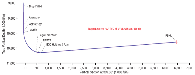
FIGURE 2
Vertical Section of Well 3 (ADP)
The solution applied in the Eagle Ford project consisted of simply replacing joints of standard SDP with lighter ADP while keeping the same BHA and well design to reduce the amount of drag friction while sliding to increase ROP and extend the lateral section.
ADP Technology
ADP is manufactured in an extrusion process, and can be produced with varying wall thicknesses along a seamless tube pipe body. This tapering allows for increased thickness and greater strength around the tool joint interface, and an upset wear band can be extruded integrally in the center of the pipe body (ADP can be fitted with any type of API or premium steel tool joint through a thermal shrink fit process). The tapering and center wear band both play a role in increasing the pipe’s resistance to bending fatigue, and to an extent, help reduce helical buckling tendencies. They also reduce pipe body wear and mitigate fatigue risk caused by bending stress.
Given the design and geometrical properties of ADP (steel tool joints, aluminum alloy body, and larger-outside diameter wear band on the middle of the pipe), advanced numerical modeling is required to fully predict the occurrence of buckling and calculate the state of stress along the pipe to avoid possible damage. In the Eagle Ford wells, torque and drag were calculated using advanced numerical modeling software (Buckling Severity Index) that considers the effects of friction, tool joint, rotation and well bore geometry in the buckling calculation.
Given the tapered geometry and lower material hardness, some relatively minor handling modifications should be made relative to normal rig operations. The first, and most critical, is to provide for tapered and nonmarking slip dies to allow a larger and more consistent area of contact between the slip and pipe. This reduces stress concentrations and the potential for imparting stress-concentrating deformations in the aluminum pipe body.
FIGURE 3
Simulated and Actual Torque Off-Bottom in Curve And
Lateral Sections
for Wells 1 (SDP) and 2 (ADP)
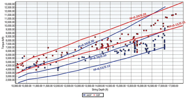
Friction factor = Cased hole/open hole
The second key consideration is for a slight relief of the elevator bushings to accommodate the larger outside diameter of the tapered ADP profile near the tool joint shoulder. In addition, soft spacers, soft slings, modified lifting elevators or lifting caps should be used to minimize aggressive contact between steel surfaces and the softer aluminum pipe body.
It should be noted that ADP does have temperature and corrosion operating limits. In general, aluminum should not be used in environments in which the pipe body will reach temperatures of 240 degrees Fahrenheit for extended periods or where pH is outside a range of 4 to 10 without considering temperature- or corrosion-related strength downgrades.
Eagle Ford Application
The design of the four Eagle Ford wells analyzed in this study included:
- Drilling a 12 1⁄4-inch vertical hole to approximately 3,500 feet;
- Setting 9 5⁄8-inch casing;
- Drilling an 8 3⁄4-inch vertical hole with a nudge section to 10,000 feet;
- Drilling a short build section at 8-10 degrees per 100 feet; and
- Drilling a 7,000-foot lateral section at 93.5 degrees of inclination.
Figure 1 shows a 3-D view of the four wells, while Figure 2 shows the typical vertical section of well 3.
FIGURE 4A
Well 2 Simulated and Actual Hook Loads while Drilling Curve and Lateral Section (Sliding Mode)
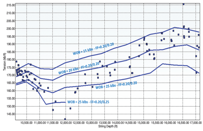
Friction factor = Cased hole/open hole
All four wells used the same BHA for the curve and lateral sections from 10,000 feet to 17,000 feet: an 8 3⁄4-inch PDC bit, a 6 3⁄4-inch steerable mud motor with a 2.0-degree bend and a 4/5 lobe stator configuration, and a 6 3⁄4-inch measurement-while-drilling tool. The drill string in well 1 used only 5-inch S135 steel pipe. In the other three wells, 180 joints of SDP were replaced with 5 7⁄8-inch 2014-T6 ADP starting directly above the BHA. The torque and drag optimization study determined the appropriate number of ADP joints in the drill string to minimize friction and reduce compression along the wells’ trajectories.
FIGURE 4B
Well 1 Simulated and Actual Hook Loads while Drilling Curve and Lateral Section (Sliding Mode)
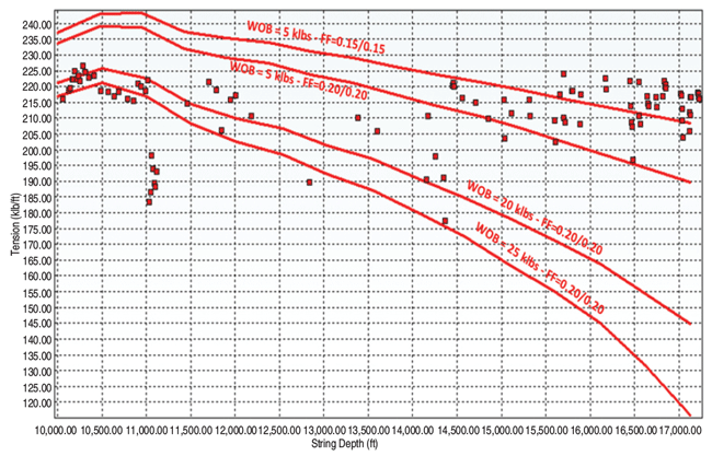
Friction factor = Cased hole/open hole
TABLE 2
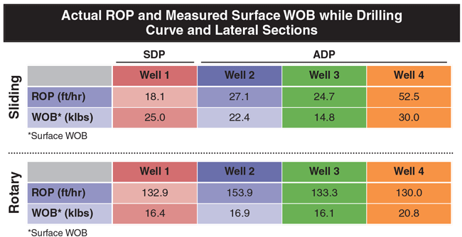
FIGURE 5
Tension/Compression Curve while Sliding at 17,130 feet
For Wells 1 (SDP) and 2 (ADP)
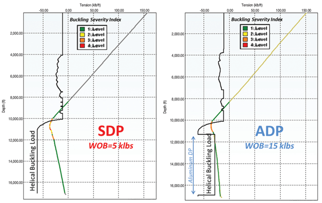
FIGURE 6
3-D View of ADP String while Sliding at 17,130 Feet
(Bending Stress and
Contact Side Force)
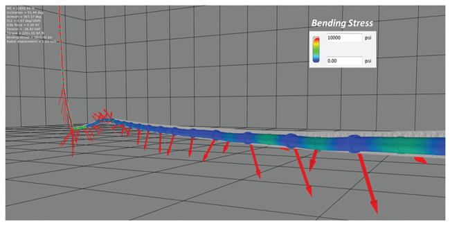
Figure 3 shows simulated and actual torque off-bottom in the curve and lateral sections of wells 2 (ADP) and 1 (SDP). The surface rotation speed varied between 70 and 80 rpm. In well 2, ADP reduced torque about 25 percent. The calibrated coefficient of friction (based on torque and drag simulations) was 0.15-0.3 for ADP and 0.15-0.2 for SDP. Additional analysis is required to quantify the effect of hole cleaning on the coefficient of friction, but it appears ADP showed its strongest advantage while drilling the second half of the lateral section.
Figures 4A and 4B show the actual and simulated hook loads while sliding with both the ADP and SDP strings, respectively, at different real WOB (15,000-25,000 pounds for ADP and 5,000-25,000 pounds for SDP).
With the ADP string, the surface-measured WOB was always larger than the real weight transmitted to the bit because of friction, especially in the sliding mode. Hook load measurements coupled to torque and drag simulations better quantified the real WOB transmitted to the bit. Based on comparisons between actual and simulated hook loads, the real WOB was about 15,000 pounds while sliding, assuming a 0.2 coefficient of friction. It is interesting to note that average surface WOB measured while sliding was about 22,400 pounds, overestimating the real WOB transmitted to the bit.
Torque and drag simulations for the SDP string showed low weight on the bit compared with ADP, especially at the end of the lateral section with only about 5,000 pounds of WOB. The calculated hook load is very sensitive to the coefficient of friction. A difference of 0.1 in the coefficient of friction can produce a difference in the hook load of more than 30,000 pounds at surface.
Improved Performance
Based on these observations and simulations, one can conclude that drilling performance during the sliding phases was better with ADP, with more efficient weight transfer to the bit producing a higher ROP (Table 2). Indeed, ROP was about 50 percent greater in well 2 than in well 1. In addition, ROP in rotary mode was 16 percent higher in well 2 than in well 1.
Figure 5 shows the evolution of tension/compression along both the SDP and ADP strings while drilling in sliding mode at the same bit depth of 17,130 feet. The hook load at surface was quite similar, despite a larger WOB on the ADP string than on the SDP string. In addition, the helical buckling limit was not exceeded on ADP, and a buckling severity index of 3.0 was reached locally in both wells in the curve, meaning that bending stress and/or contact side forces were significant enough to prevent good weight transfer to the bit.
Figure 6 shows a 3-D view of the ADP string while sliding at 17,130 feet. Note the contact side forces (red arrows) on ADP tool joints and wear bands, and the low bending stress on the pipe compared with the curve section.
The Eagle Ford test results demonstrate that the ADP string delivered better ROP performance thanks mainly to reduced torque and drag, eliminating up to two days of rig time in drilling the curve and lateral sections. In fact, comparing the three wells drilled with ADP with offset wells in the same field drilled with rotary steerable systems, it appears that using ADP with a steerable mud motor provides similar performance in terms of drilling days versus depth.
STÉPHANE MENAND is managing director of DrillScan US Inc. in Houston. Menand has 17 years of industry experience, mainly as a research and development project manager in directional drilling, drill string mechanics (torque, drag and buckling), drilling dynamics, and drill bit performance. Menand serves on the “Journal of Petroleum Technology” Editorial Committee and is associate editor of the Society of Petroleum Engineers’ “Drilling and Completions Journal.” He holds a Ph.D. in drilling engineering from Mines ParisTech.
JEFFRY K. LEHNER is technology director for Alcoa Oil & Gas in Houston. He previously managed oil and gas programs at the Alcoa Technical Center, and his career at the company includes application development for the petroleum, aerospace and defense industries. Before joining Alcoa, Lehner was a wireline services field engineer at Schlumberger. He holds a B.S. in mechanical engineering from Purdue University and an M.B.A. from Indiana University.
NIGEL EVANS is president of Ryan Directional Services, the global directional drilling division of Nabors Industries. With 38 years of experience in directional drilling and oil field services, he holds four drilling-related patents and has specialization in horizontal drilling techniques. Evans has previous managerial experience for major service companies in Latin America, Asia, the Middle East and the North Sea. He holds a degree in economics from Liverpool University.
AARON PALMER is U.S. directional operations manager at Ryan Directional Services, a Nabors company. He started his 13-year oil and gas industry career as a roustabout in the Gulf of Mexico, and has progressed to gain extensive directional drilling experience throughout major U.S. oil and gas plays. Palmer holds a B.S. in electronics engineering technology from Northwestern State University.
ARTHUR METCALFE is drilling manager at Penn Virginia Corporation. His industry experience includes serving as a drilling supervisor and drilling engineer in the Eagle Ford Shale, San Juan Basin, Permian Basin and deepwater Gulf of Mexico, and mentoring junior drilling engineers and technicians. A former reconnaissance marine and commercial diver, Metcalfe holds a B.A. in chemical engineering with minors in math and chemistry from Louisiana State University.
For other great articles about exploration, drilling, completions and production, subscribe to The American Oil & Gas Reporter and bookmark www.aogr.com.

