


Dynamic Simulations Optimize Systems Design On Stampede Project
By Leonardo Puecher, Paul Clare and Ankur Rastogi
HOUSTON–The Stampede “megaproject” is on track to achieve first oil safely, on schedule and within budget in the first half of 2018. Located 115 miles south of Port Fourchon, La., in Green Canyon blocks 468, 511 and 512, the deepwater development–estimated to cost approximately $6 billion–consolidates the Pony (3,557 feet of water) and Knotty Head (3,497 feet of water) discoveries.
Stampede contains estimated gross recoverable reserves of 300 million-350 million barrels of oil equivalent in layered Miocene intervals at true vertical depths between 28,000 and 31,000 feet, making Stampede one of the deepest fields ever developed in the Gulf of Mexico. The reservoir is a four-way structural closure segmented by faults beneath a ~15,000 foot-thick salt canopy.
In addition to the depth and geologic complexity of the 3,000-foot interval containing several pay zones, this unique reservoir system has a low gas-to-oil ratio and a low bubble point–a combination that calls for an in-well gas lift injection design. The development plan encompasses 10 total in-service wells: six producing wells and four water injection wells for reservoir pressure support.
The wells are connected through subsea well centers to a new tension leg platform stationed in 3,350 feet of water at Green Canyon Block 468. The TLP has designed daily topside throughput capacities of 80,000 barrels of oil, 100,000 barrels of water injection, 80 million cubic feet of gas lift, and 40 MMcf of produced gas export. The TLP was safely and successfully installed during the second quarter, and two rigs are now on location performing drilling and completion operations on the initial wells.
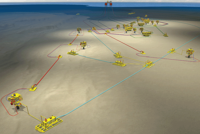
Figure 1 shows an overview of the Stampede subsea system. The layout includes two, six-slot drilling and production centers spaced about one mile apart that consist of 15,000-psi vertical trees, production manifolds and gas lift distribution units. The subsea centers are tied back to the TLP through piggable flowlines. Both the production and injection wells are being completed with multizone intelligent systems.
FIGURE 1
Stampede Field Development
Hess Corporation is the operator of the Stampede Field and holds a 25 percent working interest. Its co-owners in the project are Union Oil Company of California (Chevron), Statoil and Nexen Petroleum Offshore U.S.A., which each also have 25 percent working interests.
Dynamic Simulation
The Stampede project team identified dynamic simulation as a validation tool during the early design phase. High-fidelity, fully compositional models were developed for the subsea environment to simulate heat-transfer effects in well annuli and better understand the interaction between production fluid and gas lift injection for various startup cases. Once that model was in place, the project team identified the need to continue using topsides and subsea integrated simulation models to validate additional phases in process design and engineering.
Consequently, a multipurpose dynamic simulator (MPDS) was developed that proved to be crucial to engineering and operations. The scope of the MPDS grew as the project progressed, and it was developed for application in many phases–from concept selection and engineering studies, to control system checkout, operator training, commissioning support and engineering design and support functions for possible future tiebacks. The complexity of the Stampede development also required an effective training system for field operators. Therefore, the models developed during the engineering phase also were used for operating procedure validation and training.
Using a simulator with dynamic full-facility components (subsurface, subsea, hull and topsides) during each project phase benefitted various disciplines, from reservoir and flow assurance engineers to operations, automation and initial startup teams. The integrated model provided tangible economic benefits, leading to more informed design decisions throughout the project’s life cycle and minimizing the need for “workarounds.”
Two dynamic simulation models were developed in parallel, one focusing on the subsea system and the other on the topsides. Each was built by different delivery teams to address specific elements in Stampede’s overall design.
The subsea model (wells, flowlines and risers) was built to examine the dynamics of in-well gas lift and flow assurance. It included component tracking and a detailed heat transfer model of the wellbore to simulate the full effects of gas lift as effectively as possible. In this model, the subsea part of the development was modeled in high fidelity with a simplified view of the topsides.
The topsides model (topsides facilities and hull) was built to provide a detailed model of the main process components through the oil and gas train with a simplified view of the subsea system. It was used to verify the configuration of topsides equipment and the control system, allowing the design team to simulate the interaction of equipment and controls at both local and systemwide levels.
Example Applications
Examples of specific systems that benefitted from dynamic simulation are the compression train and the oil export pumps. In both cases, the MPDS was used to verify and fine-tune the control system so that each system operated in a stable manner through a range of simulated upsets, providing confidence in the integrated control system.
It eventually became apparent that some of the simplifications in the two models–the subsea model focused on flow assurance and the topsides model focused on equipment design and control strategy verification–did not fully show the dynamic nature of the development. For instance, as lift gas is delivered in a well, there is a recycle of gas through the two models that takes time to build up and deplete if an upset occurs in either system. Because the topsides system was simplified in the subsea model and the subsea system was simplified in the topsides model, neither accurately showed the field’s overall operation.
The design team’s solution was to combine both models into one integrated full-field engineering simulator, allowing transient conditions in either model to be carried through and influence the other and providing a better understanding of the Stampede development.
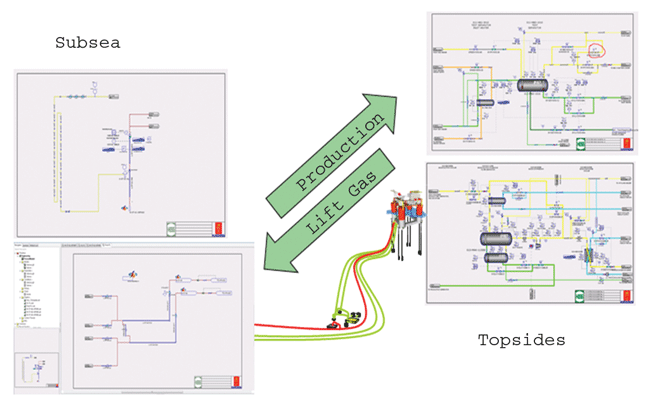
As shown in Figure 2, the subsea and topsides models become interdependent when integrated. Gas produced from the reservoir is compressed and returned to serve as lift gas. Over time, the gas builds in the system until there is 80 MMcf/d circulating through the system. An upset in topsides compression, such as the loss of one of the machines, will result in excess gas to the sales or flare lines, reducing the lift gas available and impacting well production. Because of the large volume in the system, this effect is slow to occur, as is the facility’s recovery when the compressor is restarted. Understanding this effect is important to understanding the overall operation of the facility and how the system will behave during startup and shutdown.
FIGURE 2
Interdependence Between Subsea
And Topsides Models
The ability to account for in-well gas lift and the volume of gas being recycled throughout the development was one of the primary benefits of developing the integrated model. Production rates depend on gas lift, and lift gas quantities are built up from associated gas, so the full system behavior can be observed only when both parts of the model are fully represented and linked. The MPDS also provides valuable insights into how the facility is likely to behave during startup, shutdown and upsets. In addition, topsides engineering was able to engage subsea, operations and production engineering during the design phase. This provided valuable systems validations at a time when the design could still be influenced.
Process Model
The process model was developed using the project’s piping and instrumentation diagrams as a template for the simulation graphics. The model included all the major equipment, pipe and fittings, and instrumentation. The process model for subsea, topsides and hull equipment also is connected to an emulation of the facility control system, which has the same configuration for process logic, safety controllers and operator station screens as the system used offshore.
Location and elevation information for all topsides and hull equipment and instrumentation are included in the simulator and integrated with a hydrostatic model to accurately calculate platform inclination and draft based on free deck loads, mooring line lengths, tank liquid levels and environmental conditions such as waves and wind.
The process model has three main components, each consisting of specific systems and units:
- Hull (ballast and bilge systems);
- Subsea (producing wells and completions, subsea manifolds, water injection wells, water injection flowlines, subsea manifold-to-riser pipelines, and gas lift flowline); and
- Topsides (oil separation system, cooling and heating medium systems, seawater lift pumps, waste heat recovery unit, produced water system, gas compression system gas dehydration system/glycol regeneration, chemical injection systems, high- and low-pressure flare systems, fuel gas system, and water injection skid).
The integrated simulator was used as a tool during Stampede’s design phase, but also added value in several other engineering and operational workflows. One example is transient in-well gas lift studies. Key flow assurance concerns were investigated with in-well gas lift design early in the project. The objectives were to confirm gas lift valve orifice size, confirm gas lift flying lead design, and understand well drawdown when ramping up with gas lift. These objectives became inputs for the production engineering flux model.
First production at the Stampede Field is anticipated in the first half of 2018. Targeting Miocene intervals at true vertical depths up to 31,000 feet, the Stampede reservoir system ranks among the deepest ever developed in the Gulf of Mexico. Shown here, operators on board Heerema Marine Contractors’ Aegir deepwater construction vessel use remotely operated vehicles to attach the tendons to the Stampede tension leg platform during the TLP’s safe, successful installation earlier this year. Hess Corporation is operator of Stampede, with co-owners Union Oil Company of California (Chevron), Statoil and Nexen Petroleum Offshore U.S.A.
Two gas lift restart cases were tested: unchoked, with the production choke ramped to 100 percent before starting gas lift, and choked with gas lift started before the production choke was opened (with the gas lift rate gradually ramped as the production choke ramps to 100 percent). The results showed controlling the production choke to achieve a “gentle” startup with 13 MMcf/d gas lift per well is preferred, with the orifice size ultimately controlling/limiting the gas lift flow rate.
Another example was a study of the facility’s compressor control strategy. Booster compression is used to compress incoming gas to an intermediate pressure for dehydration before sending to gas lift, fuel gas or gas sales compressors. Each compressor has its own controls. The study was conducted to determine how to control the overall compression train from inlet to outlet. The design team tested multiple control strategies under a number of scenarios, including well startup and shutdown, and spurious trips within the compression train itself.
The integrated simulator provided the design team with a platform to test numerous scenarios while designing the control system, allowing the team to fully understand how transient conditions are carried through the entire system. This was an essential tool to fully understand such a complex system.
A final example was a study of the oil export pump controls. At Stampede, the pipeline pumps employ variable speed couplings to regulate flow and pressure, as well as to start/stop the pumps as required. The configuration is unusual because there is no recycle cooler. Oil is pumped from the dry tank and metered in the lease automatic custody transfer unit before being sent by the pumps to the export pipeline. The topsides simulator was used to design the pump control system so that it remains stable through various platform throughputs as well as transients such as switching over pumps. As the design evolved, each iteration was tested on the simulator until the design team was confident of a robust design.
In another mode of operation, the pipeline pumps can be configured for pigging, requiring a very different control strategy that was again tested and proved on the simulator. The simulator also allows for testing facility turndown, especially during the startup of initial wells when oil will be flowing significantly below the facility’s design capacity. Early facility life “low flow” cases are often overlooked, but the simulator allowed the design team to consider this condition at a time that the design could be influenced to ensure no surprises at initial startup.
Testing And Validation
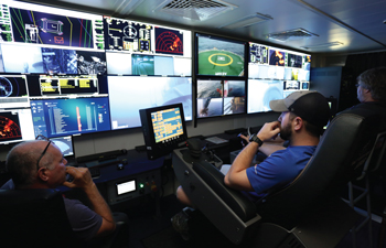
Simulator models built in the integrated engineering phase were updated to the latest process design data and connected to the control system. Programmable logic controller programs from the project were taken, and input and output points were completed between the model and PLCs. The Stampede training room has two operator consoles with multiple monitors, and one instructor/engineering station. All the control system software resides in virtual machines in a physical server host. Figure 3 shows the software architecture of the simulator system.
FIGURE 3
Simulator Software Architecture
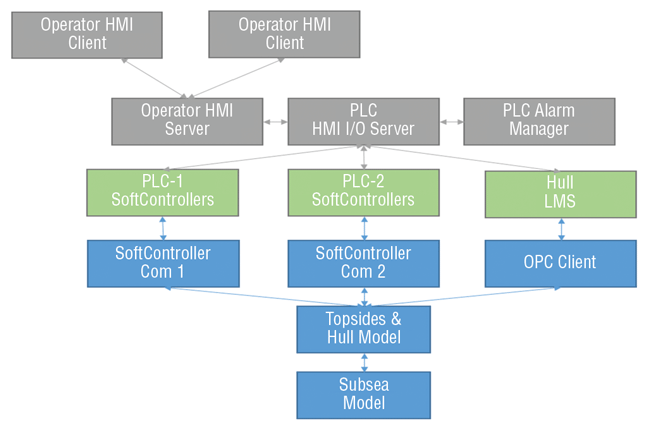
FIGURE 4
Development of Operator Training Simulator
From Engineering Simulator
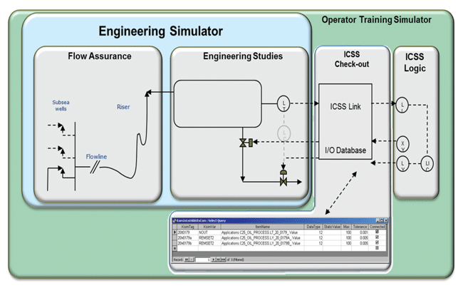
During the project’s control system integration stage, each process point (e.g., transmitters, valve control and feedback, motors start/stop and feedback) was tied to the virtual control system. Process controls implemented in the engineering phase were disabled and control was transferred to the soft PLCs (Figure 4). The simulator presented operational information using the same human/machine interface (HMI) of the actual facility. The simulator proved to be an effective tool to perform control system check-out during the pre-commissioning stage before actual startup. Check-out detected configuration errors in the PLC logic, thereby improving PLC implementation and reducing commissioning and startup offshore.
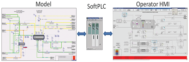
The simulator scope included a total of 18 PLCs. As shown in Figure 5, once these PLCs were integrated with the model, operator screens were used to mimic the startup of subsea and topsides processes in the virtual control system environment. The control system check-out allowed the simulator to be used to check graphic displays and navigation, verify alarm settings and trip set points, perform controller loop tuning, validate permissive logic, validate cause-and-effect matrices, and test startup and shutdown logic sequences.
FIGURE 5
Model Integration to PLCs and Operator Interface
More than 200 items related to operator HMI graphics configuration and control logic changes were identified and resolved on the simulator during control system integration and testing. Control loop pre-tuning was performed for all the topsides process systems.
A total of 85 standard operating procedures (SOPs) were developed for routine operations on the platform and validated in the operator training simulator, including 11 startup and shutdown SOPs, 20 process SOPs, 24 utility SOPs, 18 subsea and umbilical SOPs, and 12 marine SOPs.
The SOPs were developed with the required level of detail to safely operate Stampede’s complex subsea equipment, well completions and topsides facility. Using the operator training simulator during procedure development allowed the team to identify improvement opportunities that were incorporated in each SOP before a definitive version was issued.
Because SOPs were developed simultaneously with the control system revision and validation process, several cycles of feedback were necessary to solidify revisions and obtain approvals. An interdisciplinary team of process, operations and automation engineers also used the simulator to review initial startup procedures for buyback gas, oil export and well ramp up. This was particularly valuable because the simulator provided a safe environment to look at options during activities that require the facility to be operated outside its base configuration.
Operations Training
After 11 months of development, the Stampede training simulator was delivered to operations. The training plan was designed around the operations work schedule already in place: four teams in a 14-14 rotational scheme, with a crew assembled one year before anticipated first oil and four months before the platform’s sail away date.
The simulator was an integral part of operations training and competency planning, which included training modules ranging from environmental, health and safety to technical and processes. The modules were delivered as computer-based training, vendor-provided training and instructor-led training. The training allowed control room operators (CRO) to become familiar with SOPs and prepare to safely startup, shutdown and operate facility systems. At the end of the allotted training period, CROs demonstrated their competency by means of a computerized assessment tool, which documented the correct execution of the assessed SOP in both sequence and timing.
Corresponding system operating manuals also were used in the training. The manuals included detailed information about processes and equipment, as well as safety requirements, design and operating parameters for each system and subsystem, and the consequences of deviating from those parameters.
Since all control systems were modeled, CROs were trained to operate and troubleshoot the process control system, the process safety system and the emergency safety system. CROs also were trained in identifying and handling alarms, aided by a logic diagram and trending tool in the human/machine interface.
Deploying an integrated engineering simulator early in the design phase has proven beneficial on the Stampede project by linking dynamic subsea and topsides models to provide an overview of how the entire facility interacts across multiple disciplines. By connecting all the systems together–subsurface and artificial lift equipment, risers and production facilities, export pipeline pumps, etc.–the simulator has been crucial in solving the challenges the project faced. Using the complete platform model, the project team was able to identify and solve potential issues before they could become problems.

Leonardo Puecher is a facilities engineer at Chevron and is part of the Stampede project team. He joined Chevron in 2000 as a communications, instrumentation and automation supervisor in Argentina. Puecher had previously served as a communications and IT supervisor at Bridas Energy Services and an electronics technician in the Argentinean Navy. He holds a degree in electronics engineering from the Universidad Tecnológica Nacional, and an M.S. in petroleum engineering from the University of Southern California.

Paul Clare is a process engineering advisor at Hess Corporation and is part of the Stampede project team. He joined the company in 2011 as a senior process engineer after serving for nine years as a process engineer at KBR/Granherne and for five years as a senior process engineer at Snamprogetti. Clare holds a degree in chemical engineering from the University of Newcastle-upon-Tyne.

Ankur Rastogi is group manager and senior technical advisor at Kongsberg in Houston. He joined the company in 2007 as a senior process consultant and subsequently served as technical advisor before assuming his current position. Rastogi had previously served as a process consultant at Fantoft and a simulation engineer at Trident Computer Resources. He holds a B.S. in chemical engineering from the Indian Institute of Technology, Kanpur, and an M.S. in chemical engineering and an M.B.A. from the University of Houston.
For other great articles about exploration, drilling, completions and production, subscribe to The American Oil & Gas Reporter and bookmark www.aogr.com.

