


Multistage Fracturing
Permian Well Shows Benefits Of CTFS
By David Luna, Ruslan Filyukov And Otman A. Algadi
FORT WORTH–The Permian Basin is experiencing a significant increase in oil-directed horizontal drilling. In fact, according to the U.S Energy Information Administration, the Permian has far and away been the fastest growing region for horizontal oil drilling activity over the past two years, as operators target the Wolfcamp, Bone Spring and other unconventional oil formations in West Texas and Southeast New Mexico with horizontal well trajectories.
At the same time, hydraulic fracturing technology continues to evolve rapidly, with new technologies focusing primarily on making the process more efficient, cost effective and environmentally friendly. One example is coiled tubing-activated frac sleeves (CTFS), a cost-effective and efficient multistage fracture stimulation/completion system.
Although a relatively new technology, CTFS has been used extensively in Canada. Building on the experience gained with this patented technology in Canadian operations, CTFS was used to successfully stimulate a 29-stage Bone Spring horizontal well operated by XTO Energy Inc. in Lea County, N.M.
CTFS effectively reduces the required hydraulic horsepower, fluid usage, and downtime between frac stages. It is compatible with open-hole or cemented completions and provides full wellbore access without milling for unobstructed production. Bottom-hole temperatures and pressures are recorded using memory gauges attached to a CT-deployed bottom-hole assembly for post-treatment analysis and diagnostics. The system provides rapid recovery from screen-outs, minimizing downtime and adding flexibility to treatment design.
As opposed to plug-and-perf multistage fracturing, which is the predominant technique in the Permian, CTFS utilizes frac sleeves that are opened hydraulically using a CT BHA. This saves significant amounts of time between stages, reduces fluid consumption, and eliminates the need to mill out plugs to initiate production. The single frac fluid entry point allows tighter spacing of frac stages and ensures that the fracture is created at the sleeve.
As demonstrated in the Bone Spring horizontal well application, CTFS multistage fracturing is a fast, effective and efficient stimulation technique. It efficiently minimized nonproductive time, considerably reduced fluid consumption, and shortened post-frac clean-out time. All 29 frac stages were completed safely and in a timely manner, and the system ensured that fractures were created at the ports to provide effective stimulation throughout the entire lateral section.
CTFS does not involve wireline to perforate casing and initiate contact with the formation, or require dropping balls to open ports or set composite plugs to isolate each stage. Instead, it includes frac sleeves that are pressure balanced and hydraulically opened using a specially designed BHA deployed on CT, providing an unlimited number of frac stages. The sleeves are run with casing and cemented in place or attached on a liner with external packers for open-hole completions. The CT BHA is run down hole prior to starting the fracturing process.
Plug-and-perf techniques treat multiple clusters at once, which can result in uncontrollable fractures and poor overall stimulation efficiency of the entire lateral section. In contrast, CTFS is a targeted fracturing technology that improves reservoir drainage in horizontal wells by ensuring the fracture is initiated at the sleeve. It also leads to better production performance compared with other completion and stimulation techniques by increasing the number of frac stages with tighter spacing in between.
System Design
The two main parts of the CTFS system are the hydraulically activated frac sleeves and the CT BHA (consisting of a mechanical casing collar locator, packer, sand jet perforator, and pressure and temperature memory gauges for this operation). The CT BHA provides real-time monitoring capabilities of bottom-hole fracturing pressure using the CT dead string to provide more reliable data to optimize treatment on the fly.
FIGURE 1
Coiled Tubing Bottom-Hole Assembly
The casing collar locator is used to accurately locate the frac sleeves and place the BHA in the proper location. The packer is used to open the frac sleeves and provide isolation from previous frac stages.
The sand jet perforator allows a frac stage to be created where a sleeve was not installed or where an extra stage is desired. It is also used as a circulation sub to enable fluids to be circulated through the CT to surface in case of a screen-out. The pressure and temperature memory gauges attached on top of the packer measure bottom-hole flowing pressure and temperature, as well as pressure and temperature under the packer to identify communication between stages (Figure 1).
The CT-activated frac sleeves are pressure balanced and are opened by creating a pressure differential across the sleeve. The frac sleeves contain an internal valve that provides better protection from wellbore conditions and cement operations. The drive chamber and ports are filled with cement inhibitor to prevent any possible cement from setting up in the sleeve. The sleeves will not open prematurely unless there is a packer set inside the sleeve, just below the ports, and differential pressure can build across the sleeves.
FIGURE 2A
CT Frac Sleeve in Closed Position
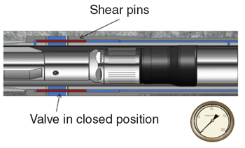
FIGURE 2B
CT Frac Sleeve in Open Position
Once the packer is set in the proper place in the sleeve, a pressure differential is created by applying pressure down the annulus of coiled tubing and the inside diameter of the casing. Once the differential pressure is created in the drive chamber, the pins are sheared and the sleeve is in the open position ready for the first stage to be fractured (Figures 2A and 2B). Once the fracturing operations are complete, the packer is unset by applying up-strain on the CT. The packer can be moved then to the next sleeve and the same operations are repeated for all installed sleeves.
Bone Spring Application
The Bone Spring formation in the Delaware Basin includes three Bone Spring sands that are topped by the Avalon Shale. The Bone Spring is stratigraphically located between the Wolfcamp Shale and shallower Delaware sands (Figure 3). The Bone Spring shows moderate porosity and low permeability.
FIGURE 3
Formations in Northwestern Shelf, Delaware
And Central Platform Sub-Basins
The horizontal well in this case study was drilled with a lateral section of 4,671 feet into the Third Bone Spring sandstone, which has a porosity range of 7-18 percent and permeability of 2 millidarcy or less. The 29-stage fracturing operation was completed in four days of daylight operations using CTFS technology.
All frac sleeves were torqued up, drifted and pressure-tested in a controlled manufacturing environment prior to shipping to location. After arriving on location, the 4.6 foot-long frac sleeves were inspected by field engineers and deployed into the well in conjunction with 51⁄2-inch casing joints. The casing and sleeves then were cemented in place.
A day before commencing fracturing operations, coiled tubing arrived on site and a clean-out run was performed using CT in conjunction with a mill and motor to clean out any excess cement. CT was pulled out of the well and the CTFS BHA was rigged up.
As a continuous pumping technique, CTFS operations required only eight to 15 minutes between stages to set the packer and open the frac sleeves with CT, keeping NPT to a minimum and allowing all 29 frac stages to be completed in 33.5 daylight hours. The average per-stage pump time was 50 minutes. The sequential treatment design for each stage included pumping a prepad of treated water, a prepad of 20-pound linear gel, a pad of 20-pound cross-linked gel, and sand-laden 20-pound cross-linked gel.
Stimulation Operations
The prepad and pad fluids of each stage were used as flush for the pervious stage to reduce water usage. Proppant concentration was “stair-stepped,” starting at 1.0 and incrementally increasing to 1.5, 2.0, 3.0 and 4.0 pounds per gallon (psa). Clean fluids used per stage averaged 1,613 barrels, pumped at an average rate of 40 bbl/minute with an average of 78,730 pounds of proppant pumped per stage.
The first stage was pumped as designed to completion. A slight change in treatment design was implemented for the remaining stages: The prepad of treated water was taken off the pump schedule. Despite the high surface treating pressure (STP) at the beginning of stages five, six and nine, the proppant substages were started as designed without the apprehension of screen-out since CT was already in the well. The rate was reduced as STP approached the maximum pressure. Once STP started decreasing, the pump rate was increased to 40 bbl/minute, as designed.
Starting proppant pumping at high STP would not be possible using plug-and-perf techniques because of the lack of contingency options in case of a screen-out. It was not possible to initiate the fracture for stage eight at first because of high STP. The frac operation was paused, and 15 percent hydrochloric acid (HCl) was spotted directly at the ports using the coiled tubing. The frac operation was then resumed and the stage was pumped to completion. Acid assisted in dissolving cement at the sleeve ports to help initiate the fracture. Therefore, acid was pumped through coiled tubing and spotted at the ports for all stages starting from stage 10 through the end of the job.
Fracturing stage 10 was challenging because of sand left in wellbore from the previous stage. However, with CT already in the well, it was possible to circulate the well clean, function test the BHA, and continue with the fracturing operation for the stage.
FIGURE 4
STP, Rate and Proppant Concentration (Stages 18-29)
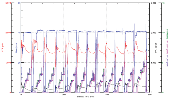
The treatment design for the last stage was changed to add a sand-laden substage with a proppant concentration of 5 psa to the pump schedule. That increased the proppant pumped for this stage to 167,485 pounds and fluids to 2,017 barrels. Figure 4 shows the STP, rate and proppant concentration for stages 18-29, which were completed in approximately 10 hours on the final day of the operation.
Since the entire lateral section was drilled within the third Bone Spring formation, the instantaneous shut in pressure was similar for every stage, averaging 4,250 psi (Figure 5A). The average STP also was similar for every stage, except that it was higher at the beginning of stages 5, 6 and 9.
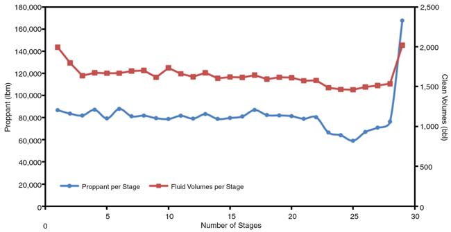
All frac sleeves were opened successfully, and all 29 zones were stimulated effectively in a single trip. The average pump rate was 39.7 bbl/minute and average surface treating pressure was 7,238 psi. The total volume of fluids pumped for the job was 47,550 barrels; the total amount of proppant was 2,371,960 pounds of Atlas 20/40-mesh sand. Figure 5B shows fluid volumes and proppant quantities for every stage.
FIGURE 5A
Average STP, Rate and ISIP (All Stages)
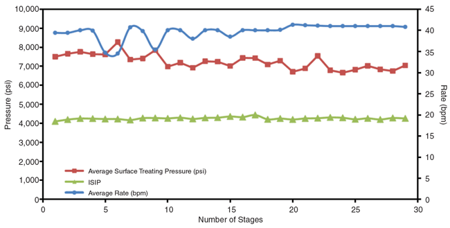
FIGURE 5B
Average Water and Proppant Used (All Stages)
The CTFS packer was used for the entire fracturing operation without needing to be replaced. It was used to open all the frac sleeves and isolate all 29 stages. It was function tested several times between stages to ensure that it was working properly.
Bottom-Hole Data
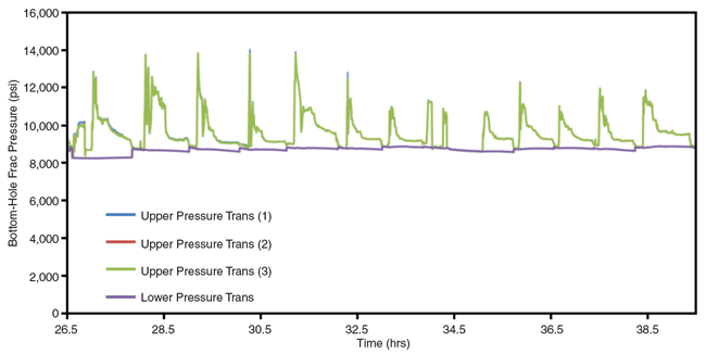
The bottom-hole pressure and temperature data recorded using the memory gauges assisted in post-job performance analysis and in optimizing future fracturing treatment designs for neighboring wells. As noted, two memory pressure transducers were deployed above the packer and one below the packer as part of the CT BHA. The lower pressure showed a straight line during the fracturing process, indicating that the packer was holding pressure and there was no communication between stages.
Figure 6 shows how bottom-hole fracturing pressure varied from one stage to another for stages 12-29. In the case of a multicluster plug-and-perf completion, most fluids are placed in the clusters that require less fracturing pressure, leaving some clusters unstimulated and unable to contribute to production.
FIGURE 6
Gauged BHFP (Stages 12-29)
Cross-linked fracturing fluids contain breaker chemicals to help break the system and assist in flow back. A breaker test is always run at the formation conditions prior to starting a job to determine the required breaker concentration. Knowing the exact formation temperature gives a more reliable breaker concentration for the fracturing fluid. Having downhole temperature pressure data allowed the operator and service provider to close the feedback loop on fluid design during the post-job analysis phase and further optimize future treatment designs.
With plug-and-perf fracturing operations, the Bone Spring formation typically is completed in 10 frac stages. That normally requires an average of 65,200 barrels of water pumped at high rates to treat multiple clusters at once and considerable NPT between stages to pump down a wireline BHA. A typical treatment requires on the order of 11,600 hydraulic horsepower (HHP). Including prep work and post-frac mill out of composite plugs with CT or a workover rig, a 10-stage plug-and-perf operation in this area takes five days on average.
On the other hand, the CTFS operation used less water because of the reduced flush volumes required with the 2.0-inch CT inside the 51⁄2-inch casing. Post-frac clean-out time also was reduced by not having to drill out plugs, balls or seats. The casing was clear of any obstructions, as verified by a clean-out run. CTFS helped save even more time on acid spotting by pumping it down the CT during the 4.0-psa sand stage and flush stage. HCl was placed within one barrel from the bottom of the CT once, so that it was ready to be spotted at the sleeve when the packer was set for the stage.
CTFS also saved acid volume by pin-pointing the acid out of the jet nozzle across from the open sleeve. This allowed the concentrated acid to dissolve any material that blocked the flow from the sleeve to the formation. In addition, CTFS required less HHP. The average HHP required for the operation was 7,000 horsepower, substantially reducing the footprint on location since less pumping equipment needed.
DAVID LUNA is a production engineer for XTO Energy in Midland. Before joining XTO in 2011, he served at Read & Stevens as an operations engineer for drilling, completion and production operations in Southeast New Mexico. Luna began his career as a logging engineer at Schlumberger. He holds a B.S. in petroleum engineering from Texas Tech University.
RUSLAN FILYUKOV is an operations engineer at XTO Energy in Midland. He joined the company in 2014 after serving nearly five years at Baker Hughes Inc., joining the company as a field engineer in 2010 and subsequently working as a district engineer, a regional engineer, and most recently, completions engineering manager for the Permian Basin. Filyukov holds a B.S. in mechanical engineering from Texas Tech University and is currently working toward completing an M.B.A. from Texas Tech’s Rawls College of Business.
OTMAN A. ALGADI is a district technical supervisor at Baker Hughes’ pressure pumping product line in the company’s office in Odessa, Tx. He joined the company as a well stimulation field engineer in 2012. He designs and oversees stimulation treatments, ensures quality control on well sites, and provides technical and operational support to Baker Hughes’ stimulation team in the Permian Basin. Algadi holds a B.S. in chemical engineering from Tripoli University and an M.S. in petroleum engineering from Texas Tech University.
For other great articles about exploration, drilling, completions and production, subscribe to The American Oil & Gas Reporter and bookmark www.aogr.com.

