


Production Facility Design
Simulation Workflow Optimizes Facility Design For Producing Multiwell Pads
By Michael W. Conder and April D. Schroer
DENVER–In tight oil plays such as the Niobrara, Bakken and Eagle Ford, multiwell pads with four or more high-volume horizontal wells–often producing multiphase liquid and gas streams–require production facilities that approach the cost and engineering sophistication of full-scale natural gas processing plants.
Facility designs for conventional vertical oil fields entail comparatively limited mechanical engineering and minimal gas handling process considerations. With one well per pad, basin-specific standardized designs with “one-size-fits-all” equipment typically are sufficient. However, the advent of multiwell pads in horizontal plays has transformed the size and complexity of pad-level processing equipment into significant production facilities that rival the cost and engineering complications of full-scale natural gas processing plants.
Ever-stricter clean air requirements also are impacting trends in engineering pad production facilities, leading to improved production and extensive vapor recovery of flash gas to minimize or eliminate venting. This trend is further compounding facility design challenges that already are challenged by low oil prices, forcing a revised focus on reducing the capital cost of production facilities to improve overall production economics. As a result, new facility projects have transitioned quickly from being schedule-driven to cost-driven, and optimizing gas handling has become critical to recognizing the economic benefits of tight oil development.
These tighter process design requirements, in turn, mandate new approaches to engineering production facilities. That includes making better use of available information, such as pressure/volume/temperature (PVT) data and implementing advanced oil characterization and simulation methods that are not necessarily familiar to many onshore facility engineers.
In a conventional oil field with vertical wells, oil typically is produced through a manual choke into a low-pressure heater-treater (a vertical or horizontal three-phase separator with a maximum pressure of 75-125 psig). Oil and water are directed to tanks vented to the atmosphere, while the resulting flash gas is sent to a gathering system, vented or flared (Figure 1A).
FIGURE 1A
Typical Traditional Well Pad (Single Vertical Well)
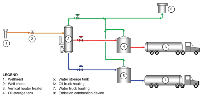
FIGURE 1B
Typical Multiwell Pad (Four Horizontal Wells)
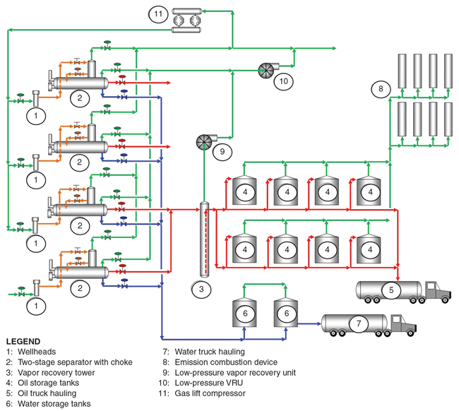
In contrast, Figure 1B shows a typical horizontal pad with four wells, although eight, 16 or even 32 wells can be included in a single facility. Multiwell pad production facilities include dual-stage horizontal separators; a high-pressure, two-phase separation stage (HPS), followed by a low-pressure, three-phase separation stage (LPS). The bulk of the gas typically is produced in the high-pressure stage at gathering system pressures ranging from 50 to 500 psig. The LPS flash typically operates at 15-50 psig and produces smaller volumes of high-Btu gas, which is then recovered by a vapor recovery unit.
Recovering Flash Gas
Produced oil from the separators carries flash gas, and the large volumes of oil produced from multiple horizontal wells on a single pad push the limits of allowable volatile organic compound emissions. The lowest-cost design option is to flash the oil to the storage tanks, then recover the vapors with a VRU compressor.
While VRUs can operate at tank pressures of less than one psig, it is nearly impossible to do so without creating a vacuum that pulls air into the flash gas. This oxygen can exceed the typical 10 parts per million pipeline specifications in midstream processing units. If the gas has some amount of hydrogen sulfide, there is additional risk of corrosion and solid sulfur deposition in downstream piping and equipment.
Vapor recovery towers (VRTs) have been introduced to provide a positive suction pressure to VRUs and act as a liquid seal to prevent air ingress into the flash gas. The towers are essentially empty vertical vessels operating at three-five psig. Oil flows into the top, the flash gas separates, and the oil exits though a dip tube (or P-trap) near the bottom of the vessel. The oil flows up the dip tube and gravity drains to the storage tanks, providing a positive seal against air ingress into the flash gas.
A small amount of flash gas is generated as the oil flows into the tanks at essentially atmospheric pressure. Some additional flash gas may be generated from tank weathering and incoming oil displacing gas, but this small amount of flash gas is routed to enclosed combustion devices (ECDs) to minimize VOC emissions.
The design shown in Figure 1B is one of many variations in basic pad gas handling design. Gas handling technology is evolving continually and designs can vary significantly even among individual companies in the same basin, depending on specific requirements or restrictions. Design variations include remote well pads with individual liquids and gas flowlines to centralized production facilities; pads with production separators and a single multiphase flowline for oil, water and gas; and various combinations of bulk and test production separators.
For engineers tasked with designing production facilities for high-volume horizontal well pads, selectively using PVT data, coupled with modern process simulation tools and a solid understanding of well operational requirements, can lead to tighter and more economical designs.
Facilities costs typically represent 10-25 percent of overall development costs, but any reductions in capital and operating costs will help improve well economics and increase ultimate recovery. Lower commodity prices make it more important than ever to use the most appropriate data and best-available technologies to optimize facilities and maximize recovery.
Simulations Using PVT Data
Reservoir and production engineers frequently run full PVT analyses to use in planning field development strategies. A PVT analysis is based on sampling an oil well early in its life, analyzing the samples, and measuring and projecting a number of fluid properties important to completion design and production operations. However, PVT data can also be used for numerical modeling to optimize facility design and minimize the risk of either undersizing or oversizing a facility for a given application.
PVT samples are taken at the surface separator, since it is difficult and expensive to get a representative sample of the actual reservoir fluid from the bottom of the wellbore. The samples are recombined in the lab to be representative of the reservoir fluid, using flow data to obtain the gas-to-oil ratios. The original and recombined samples are analyzed by gas chromatographs, resulting in carbon number (CN) analyses that typically include nitrogen, carbon dioxide, hydrogen sulfide, and hydrocarbons with CNs ranging from C1 (methane) to components as heavy as C24, C30, C36, and even higher for heavier crude oils.
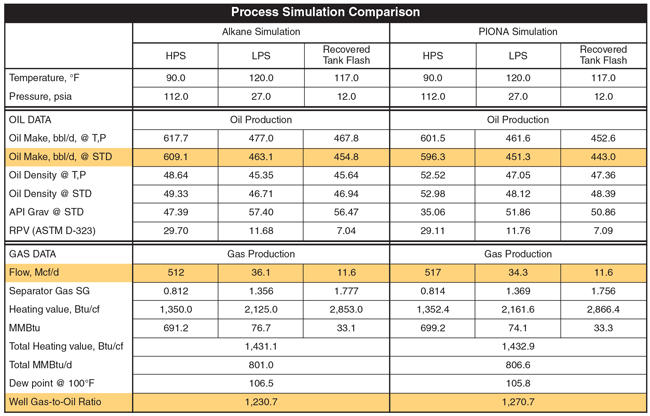
TABLE 1
In facility engineering design, PVT analyses can be used to predict gas handling requirements for a pad or field, with the reservoir fluid run in a process simulator to predict gas volumes and various flash temperatures and pressures. The typical PVT analysis only provides CN totals and does not break down percentages of paraffins, isoparaffins, olefins, naphthenes or aromatics (PIONA). While reservoir engineers can request a PVT analysis that includes the full range of carbon chains/aromatics, it is more expensive and not a common practice. This has left facility engineers with the option either to make gross guesses about the breakdown of these components, or to use simple straight-chain paraffins in simulations.
Some process simulation software developers have taken up the challenge by developing calculation techniques that mimic the effects of the various hydrocarbon species. We have performed a study using one such technique developed by the Virtual Materials Group for its VMG Sim™ system to analyze PIONA. This technique is relatively new and suitable for a wide variety of field and refinery oil handling and processing.
The subject crude oil was characterized using only the PIONA components and simulated a typical shale oil facility using these process simulation data as well as straight CN (alkane) data. As shown in Table 1, there was little difference in the calculated gas production between the two techniques, but there was a notable difference in oil properties. This would not normally impact gas handling equipment directly, but relying on inaccurate predicted oil properties may result in requiring an unnecessary stabilizer to reduce the oil gravity to a safe or required level for transporting by rail or pipeline. Off-gas flow from such a stabilizer would impact facility and gas handling designs.
PVT data should be used with caution to reduce the risk of errors or inaccurate modeling. The predicted reservoir fluid data are “second hand” from theoretical combined gas and oil streams calculated from chromatograph analyses of individual streams. A more accurate reservoir fluid for process simulations may be developed using the actual chromatograph analyses of the original samples and the oil and gas flow rates to recreate the reservoir fluid.
In addition, facility engineers tend to run process simulations using mole percentage data while raw chromatograph data uses mass percentage. PVTs calculate the mole percentage using assumed molecular weights for each of the CNs, introducing another level of uncertainty. Accordingly, engineers should use mass percentage information instead of mole percentage. It also should be noted that PVT analyses in process simulations do not always provide accurate properties with high-paraffin oils. For example, oils often contain parrafins with much higher molecular weight components than those reported in PVT studies.
GOR Analysis
Gas-to-oil ratio information normally is developed from analogue offset wells for facilities engineers to use in designing gas handling equipment in shale plays. Although the GOR is developed from actual data, the operating conditions of the wells can strongly influence data accuracy, and the design of pad and downstream gas handling/processing equipment. GOR depends on the operating temperature and pressure of the primary oil and gas separator, additional lower pressure flashes of the oil, the existence of vapor recovery, and conditions at the oil measurement (frequently on-pad tankage).
TABLE 2
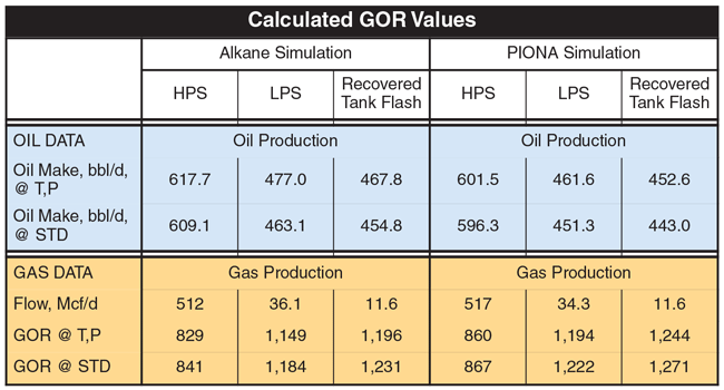
TABLE 3
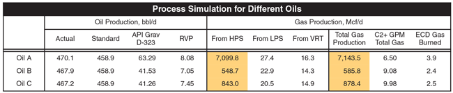
TABLE 4
In many cases, GOR is based on oil measurement either at the primary separator, or at the tankage using production numbers for the well. Gas measurement typically is taken at the primary separator conditions, and only rarely is adjusted for vapor recovery, preventing closure of facility material balances. Table 2 compares the GOR values from alkane and PIONA simulations of a typical shale oil well using the same data as in Table 1.
GOR information from production reporting typically uses only the main gas and oil flow data from HPS. These numbers can be incomplete and misleading. The GORs shown in Table 2 were calculated from the predicted oil flows and cumulative gas production. The total GOR for the well that uses total gas capture and final oil volumes (third column) is almost 50 percent higher than the typical GOR (first column). Inaccurate GOR data can mislead facility engineers into underdesigning individual well equipment as well as downstream gathering lines, compression and gas processing facilities.
Example Simulations
Table 3 presents summaries of simulations using PVT data for three oils in the Denver-Julesburg Basin. The oils were selected on the basis of the PVTs of reported stock tank API gravities (61.3, 49.6 and 35.8 degrees for oils A, B and C, respectively). Oil B is the same as used for the alkane/PIONA comparison in Table 2. Process simulations were run for each of these oils based on the same design parameters:
- Total oil production of 458.9 bbl/d;
- HPS temperatures and pressures of 90 degrees and 112 psia (100 psig), and LPS temperatures and pressures of 120 degrees and 37 psia (25 psig);
- VRT pressure of 15 psia (3 psig);
- Storage tank/ECD pressure of 12 psia (0 psig); and
- 350 Mcf/d of gas lift for oils B and C, with no gas lift required for oil A.
Table 3 shows the simulation results calculated on a single-well basis (values for larger multiwell pads are an arithmetic multiple of these values times the number of wells feeding a facility). The wide range (about 1,200 percent) in HPS production highlights the differences in GOR. In contrast, LPS gas volumes from oil production vary by only 25 percent. The design for flash gas handling equipment is obviously strongly dependent on total oil production and significantly less dependent on GOR. This allows facilities engineers to simplify the design of gas handling facilities, sizing equipment based on predicted oil production rates.
Although these simulations are for the D-J Basin, oils produced in other basins show similar trends. The flash vapor handling requirements vary much less between different oils than the HPS gas handling requirements.
The equipment required to recover flash gas is expensive, adding both cost and complexity to production operations. Some unconventional oil plays have simply flared produced gas, but regulations in states such as North Dakota now require operators to capture certain percentages of overall produced gas. The good news is that flash gas and vapor recovery can have a positive impact on production economics.
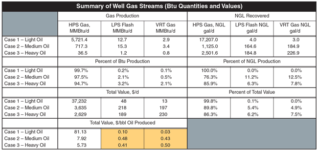
Table 4 shows the production values of the main gas (HPS) and flash gases (LP/VRT) for the three D-J Basin oils at a flash gas basis pressure of 75 psig. It also includes relative values of each of these streams, based on dry gas and natural gas liquids prices for the Rocky Mountain area. While the flash gases from heavier oils with lower GORs provide only 3-6 percent of the total produced gas volume, they can provide 10-14 percent of the total gas revenue of the well and add about $1 a barrel of oil to total well revenue.
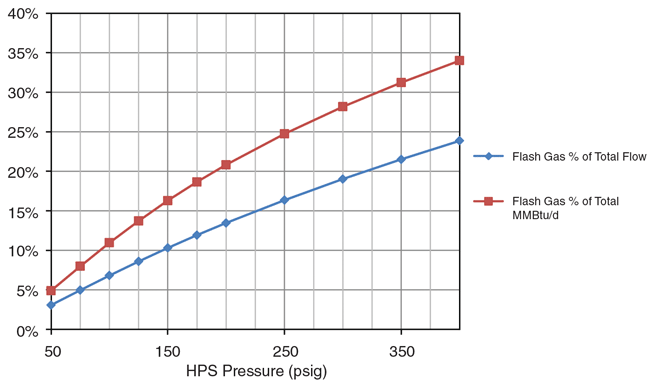
In some cases, flash gases can provide even higher revenues. For instance, if a well has to produce against higher gathering line pressures, the HPS gas volume and Btu content per cubic foot will be lower while the flash gas volume will be correspondingly higher. The total gas volume is relatively constant, since all the oil eventually is flashed at the same pressure in the VRT.
Figure 2 shows the volume of flash gas increasing with increasing HPS pressure, with total Btu production increasing even faster. At an HPS pressure of 75 psig, the flash gas is about 5 percent of the volume and 8 percent of the Btu value. At 250 psig HPS pressure, this triples to 16 percent and 25 percent, respectively. The value of the flash gases at these higher HPS pressures can add $2.50-$3.00/bbl of oil to total well revenue.
FIGURE 2
Gas Lift Design
One near-universal characteristic of shale oil wells is the need for some sort of artificial lift to produce the liquids. Operators are using a number of techniques, including electric submersible pumps, rod pumps and jet pumps. But gas lift is the one technique that most commonly impacts facilities engineering. Although simple in concept, the equipment required to inject a high-pressure gas stream and increase overall gas velocity enough to carry produced water and oil to the surface is technically complex.
The injected gas normally is separated on the surface, compressed, cooled and reinjected into the well. A common guideline for adequate gas lift in wells with 2 3⁄8-inch production tubing is 350-400 Mcf/d per well, with pressures ranging from 600 to 1,400 psig. The facility engineer is normally responsible for designing gas lift surface equipment.
Typically, this involves installing compression on the well pad to compress a portion of the well’s produced gas as lift gas. This can lead to large numbers of small (500-horsepower maximum), localized compressors. Because steep decline rates give each well a limited production life where gas lift is beneficial–ranging from a few months to perhaps a few years–these installations are temporary and the compressors tend to be leased.
Many companies are moving toward more centralized gas lift compression using fewer, but higher-horsepower units to reduce capital cost and lease cost per horsepower. Central compression does require installing gas lift lines and larger gathering system capacities to handle the recycled lift gas, but these extra costs are balanced by allowing permanent gas lift compression facilities and lower capital costs to provide lift gas to new wells.
One of the drawbacks to central gas lift systems is the potential for liquids handling problems. Most gas from shale oil wells is relatively rich (1,200-1,700 Btu/cubic foot). At high operating pressures and low ambient temperature conditions, this rich gas can result in hydrate problems if it is not dehydrated before leaving the central compression site. Liquids also can condense over longer piping runs, creating liquids handling problems at the well pads. These problems can be related to allocation and/or royalty difficulties as well as physical handling problems.
Dew point units can be employed to prevent liquids problems, and the recovered liquids can be a secondary income source–especially for companies that deliver gas to third-party processors.
TABLE 5
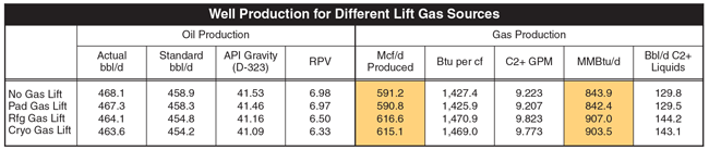
As shown in Table 5, dew pointing the lift gas actually increases the total gas and liquids delivered to downstream processing plants. This is because of the nature of the lift gas system. The “dry” lift gas mixes with the produced oil and gas from the well, effectively stripping some of the lighter ends from the oil. This helps slightly stabilize the oil and reduce its API gravity. In this example, using processed lift gas increases total MMBtu production by 7 percent and total ethane-plus liquids by 10 percent while reducing the total oil volume by only 1 percent.
Optimizing Gas Handling
Even the best facility design can be “sabotaged” by unforeseen mechanical details. The smallest item sometimes can create big operating problems. An example is snap-acting oil and water dump valves, which are standard on many separators. Snap-acting control valves create flows in vapor recovery systems that have wide variations within short periods. The gas handling equipment, especially VRUs, need to be able to handle this.
A VRT does provide dampening of the gas flows, but on pads with multiple wells, the design needs to allow for a situation in which all production separators dump oil at the same time. Increasing the overall height of the VRT (extra height above the highest oil level), including a relatively large suction drum on the VRU inlet, and converting to throttling-style control valves all help minimize potential carry-over problems.
VRT pressure control is critical also. VRTs typically run at pressures of three-four psig. Too much pressure will blow out the liquid oil seal, letting the flash gas go directly into the tanks. A pressure control valve set at six psig that sends the VRT flash gas directly to the ECDs will keep the oil seal in place if the VRU overloads or shuts down.
Flash gases are very heavy and subject to condensing at moderate to high pressures. We recommend VRUs be fitted with temperature controls on the discharge coolers that can maintain cooler outlet temperatures up to 150-200 degrees to minimize liquid dropout and potential high gas recirculation from a liquid cascade.
Many VRUs are designed to shut off on low suction pressure, then automatically start as suction pressure increases. On a VRU handling VRT flash gas, this sudden start can momentarily reduce the inlet pressure to vacuum levels, allowing oxygen ingress. Normal control schemes designed to maintain suction pressure by recycling compressor discharge gas are problematic in low-pressure VRUs since they could lead to the same potential high gas recirculation from a liquid cascade.
A better control scheme is to use a slipstream of leaner, high-pressure gas from the production separator to provide gas to maintain VRU suction pressure at one-two psig. This keeps the VRU running constantly to minimize oxygen ingress, and also helps clear out very rich gas that may condense when a VRU cycles off.
The D-J Basin facility described in this article captures 90-95 percent of the flash gas from the oil, with only a small amount of gas flowing to the ECDs. The capture rate depends on the VRUs functioning with no interruption in service. In practice, VRUs are not as reliable as most gas compressors and often have run-times of 90-95 percent. Most multiple-well facilities cannot have this much rich gas venting to atmosphere without limited oil throughput because of VOC emission limits. Therefore, enough ECD capacity should be provided to handle the full amount of oil flash vapors (low-pressure separator, VRT and ECD flash gases).
Operational Flexibility
Any facility should be designed for operational flexibility. One of the characteristics of shale oil wells is a rapid production decline within the first 12 months. The typical decline is in the 65-75 percent range, with long-term oil production at less than 25 percent of the 30-day initial production rate. Flash gas volumes are a direct function of the oil production rate, so gas systems on multiwell pads can quickly become oversized.
This can be offset in two ways. First, a multiwell pad can be fed with additional oil from new wells to keep the gas handling systems at a sufficient operating level. Second, systems can be designed with multiple operating units, such as two parallel VRUs sized for 50 percent of the gas flow, or multiple ECDs. This allows surplus equipment to be moved to new pads as needed.
Well facilities normally are designed for peak IP rates. This usually is not a problem for pads with one or two wells, but can lead to high costs and unused equipment for pads with more wells. One strategy to maximize the use of these facilities and minimize cost is to offset drilling. For example, in wells with 65-75 percent first-year declines, drilling and producing groups of four wells every six months instead of drilling all 16 wells at the same time can reduce the size of the gas and liquids handling equipment by 25 percent or more.
There are numerous opportunities available to improve and optimize the design of gas-handling facility equipment. It is important to use this period of low oil prices and reduced activity to minimize the capital cost of production facilities and improve overall well economics.
PVT analyses provide essential data for modeling the well fluid properties needed to design gas handling equipment at multiwell production facilities. More specifically, PIONA characterizations using PVT data give design engineers critical insights on nonalkane structures to allow more accurate modeling of the true fluid characteristics, ultimately leading to better and more economic production facility design over the full life cycles of tight oil assets.

Michael W. Conder is a senior staff technical advisor for Denver-headquartered Bonanza Creek Energy Inc. He has 35 years in engineering design and operations, and has worked for design engineering firms such as Ortloff Mountain States Corporation, The Pro-Quip Corporation, Propak System Ltd., Bateman Engineering and Pearl Process Systems, as well as for operating companies including Maple Gas, Vessels Energy, Duke Energy Field Services, Samson Resources Company and Berry Petroleum. Conder also has managed a gas gathering and processing facility and is co-inventor for a patent related to carbon capture technology. He has written several articles for technical conferences and magazines, and serves on the Laurance Reid Gas Conditioning Conference’s Advisory Committee. Conder holds a B.S. in mechanical engineering from the University of Arizona.

April D. Schroer operates a consulting company focused on project engineering, project management, and production facilities design and optimization. She has more than 20 years of experience in the oil, gas and refining industries in project engineering and management, engineering design and operations, process safety management, and facility optimization. Schroer previously worked for operating companies such as Noble Energy and ConocoPhillips, as well as Pearl Processing Systems. She is also active in promoting green technology such as LNG usage and design, and integrated syngas technology. Schroer holds a B.S. in chemical engineering from Arizona State University.
For other great articles about exploration, drilling, completions and production, subscribe to The American Oil & Gas Reporter and bookmark www.aogr.com.
 Advanced Cyclone Technology. Discover More.")
