


Trends Take Fracturing ‘Back To Future’
By Kevin Fisher
HOUSTON–In the popular 1985 movie Back to the Future, the lead character, Marty McFly, said, “Yeah, well, history is gonna change.”
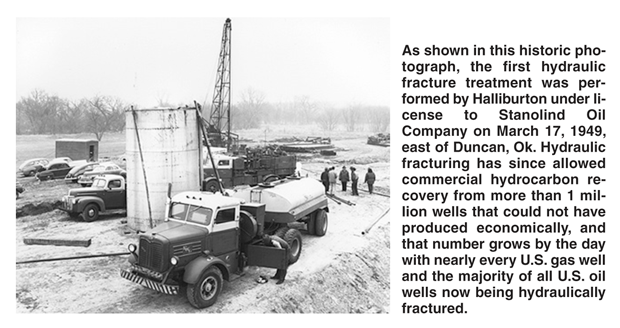
Jump back in time to March 17, 1949. A team composed of Stanolind Oil Company and Halliburton personnel converged on a well 12 miles east of Duncan, Ok., to perform the first commercial application of hydraulic fracturing. Later the same day, Halliburton and Stanolind personnel fractured another well near Holliday, Tx. The technique was developed and later patented by Stanolind (later known as Pan American Oil Company) and an exclusive license was issued to Halliburton to perform the process. Two Stanolind inventors filed separate patents on New Year’s Eve, 1949. In 1953, the license was extended to all qualified service companies.
These first applications of hydraulic fracturing technology were not met with fanfare or headlines. History, however, is changing because it is now clearly understood that the oil and gas industry in the Western Hemisphere has not been the same since that fateful date.
Fast forward to 2012, and hydraulic fracturing has allowed commercial hydrocarbon recovery from more than 1 million wells that would not have produced as economically, if at all. Moreover, it was hydraulic fracturing that ushered in the age of unconventional resource plays, beginning with “light sand fracs” in vertical Cotton Valley and then Barnett Shale wells. Eventually, Barnett operators combined multistage hydraulic fracturing methods with horizontal drilling, and the ultratight Barnett suddenly became a prolific gas producer. Gas shale and tight oil resource play development took off all across North America, opening a vast new base of economic oil and gas resources.
A hydraulic fracturing treatment increases the contact area with the reservoir, which accelerates oil and gas production so that a well can produce more in a few months or years than it would have produced in decades, or in the case of ultralow-permeability shales, centuries. Nearly every natural gas well in the United States, and more than 60 percent of all U.S. oil wells, according to some estimates, are hydraulically fractured today. Most of these wells could never be drilled or produced profitably without the application of hydraulic fracturing.
Maximizing Reservoir Contact
A hydraulic fracturing treatment utilizes water, propping agents such as sand, and chemicals to create and “prop open” a conductive crack that connects a large portion of the reservoir with the well bore. Throughout the 1950s-60s, the technical achievements in fracturing consisted primarily of developing fluid systems that could carry increasingly larger volumes of sand. In the 1970s, the term “massive hydraulic fracturing” entered the lexicon with the use of extremely viscous cross-linked gels that could carry very high concentrations of proppants. The high concentrations of proppant allowed an ever-increasing fracture conductivity, which provided a more conductive pathway for oil and gas flow to converge into the well bore.
FIGURE 1
Completion Designs and Reservoir Contact Area
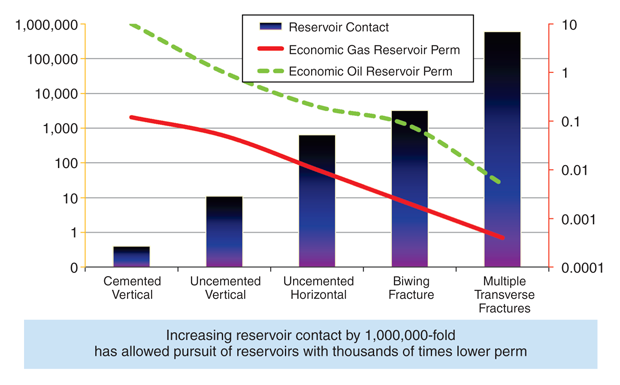
Courtesy: Mike Vincent, SPE 146376
The large contact or inflow area created by hydraulic fracturing connects a larger portion of the reservoir with the well bore. Figure 1 illustrates how various completion designs affect the reservoir contact area. The superimposed curves show the relationship of permeability needed for a given completion style.
To get similar production, the lower the permeability of the reservoir, the larger that contact area must be by about the same amount. In other words, if permeability is lower by an order of magnitude, then the fracture surface area must be higher by an order of magnitude.
Those massive hydraulic fracture treatments of the 1970s placed similar per stage volumes in vertical wells to what is now being placed in a single stage in a typical horizontal shale well. Today’s 10-100 nanoDarcy shale gas reservoirs typically require 10-50 frac stages to be performed on a single well bore. By some estimates, more than 2.5 million frac treatments have been pumped, and many oil and gas fields–particularly in North America–simply would not exist had it not been for the advent of hydraulic fracturing.
Fractures placed in a conventional reservoir generally are described as a simple bi-wing crack that bisects the well bore (probably more because of the simplicity of modeling a single simple crack versus attempting to model complex, multiplanar growth). From various fracture mapping technologies and mine-back experiments that provide a more detailed look at how fractures grow, the industry’s perception of fracture geometry–particularly fracture geometry in shale reservoirs–has changed to that of a network, or “fairway,” of fractures, rather than a single simple one.
Fracturing Design
The earliest fracturing operations consisted of gelled lease crude and/or kerosene or gasoline as the fluid base, along with screened river sand as the proppant. In the early 1950s, water-based frac fluids were utilized successfully in many areas. As evolving fluid chemistries became better suited to carry higher proppant concentrations, fracture service companies became known and differentiated for their chemical additives. Typical fracturing additives consisted of various gelling agents, biocides, surfactants, scale-inhibiting agents and gel breaking additives. A viscous gel, while useful in carrying high concentrations of proppant down the well bore and into the fracture being formed, is not ideal for the productivity of the well and must be “broken” so that the gel residues can break apart and flow back during the fracture cleanup phase.
The race to achieve higher gel loadings, higher proppant concentrations and more complex breaker systems continued well into the 1980s, with fracturing treatments becoming more complicated to execute and more expensive to pump. Even with the massive amounts of proppant being pumped and the gains in fracture fluid chemistries being realized, many reservoirs did not respond optimally to those “state of the art” (for the era) treatments.
In the mid- to late 1990s, Union Pacific Railroad Corporation began experimenting with a “new” idea in the low-permeability, gas-producing Cotton Valley Sandstone of East Texas. That new (actually old) idea was “water fracs.” Initially, the idea was to lower the fracturing cost and hope for similar production. What was discovered is that some areas of the field produced about the same amount of gas with much cheaper fracs while other areas produced even better with the lower cost water fracs. Thus, an old technique became new again.
It was “frac to the future,” so to speak.
Soon after, another operator, Mitchell Energy, saw the improved results and lower costs achieved in the Cotton Valley and decided to adopt this same “new” fracturing strategy in the Barnett Shale in the Newark East Field in the Fort Worth Basin. The first couple wells were not successful, but Mitchell Energy ultimately found the formula for what was termed “light sand fracturing,” where only water, low concentrations of sand, a little biocide, friction reducer and surfactant created massive networks of fractures to achieve tremendous surface areas in this nanoDarcy rock (which had been only moderately productive for 17 years).
As one can imagine, because of the lack of damaging gels and the fact that the thin fluids can “finger” into smaller fissures and natural fractures, water fracs created far more fracture surface area than conventional gel frac treatments. And those large surface areas, while only lightly propped, were connected just enough to the well bore to be able to access larger portions of the reservoir.
As an additional benefit, there was no gel damage to clean up. The fracture networks first “discovered” on these Barnett wells were created through a combination of new induced hydraulic fractures and a cross-cutting natural fracture system coupled with thin fluids (water fracs) that could reactivate those natural fractures, adding to the total obtained, stimulated reservoir volume.
Prior to the introduction of light sand fracturing, the Barnett was only commercially viable because of a favorable gas supply contract. With the adaptation of the water frac technique, however, it became very profitable. Water fracs, or light sand fracturing treatments, as Mitchell Energy called them, were here to stay, at least in the ultralow-permeability natural gas plays.
Horizontal Drilling
Within a few years of pumping the first light sand fracs in the Barnett, Mitchell Energy implemented the second major change in completion technique: combining multistage water fracs with horizontal drilling. The earliest Barnett horizontal wells had between one and three frac stages pumped per lateral, but rapidly began to increase to the point where today 15-20 stages per horizontal lateral are common and some wells receive 50 or more frac stages.
In addition to drilling horizontally, the completion hardware and techniques are continually evolving. From those first “open-hole” fracs in the horizontal sections through preperforated liners to cemented liners with “plug-and-perf” completions, and then to open-hole packers and sliding sleeves, the move in completions has generally been to create more and more fracture initiation points along a lateral. The idea is that more fracture initiation opportunities lead to a higher density of fractures initiated, which means larger contact areas created.
Leap forward with water fracs through the late 1990s up until about 2008. With the advent of horizontal wells and multistage fracturing utilizing water fracs, the United States was in a natural gas “boom.” Suddenly, reservoirs in which the presence of natural gas was well known, but economically unrecoverable, found the key. In low- and ultralow-permeability unconventional gas plays, water fracs became larger, and stage counts per foot of lateral increased to create a more dense fracture network. Gas drilling was accounting for almost nine of every 10 active rigs, and U.S. gas production began to grow again after years of annual declines.
Each basin came to have its own set of parameters influencing the frac design and ultimate recoverability. Changes in kerogen content, total organic content, rock brittleness, thermal maturity, in situ pressure, formation thickness, permeability, porosity, degree and variability of natural fracturing all influenced well spacing, lateral lengths and frac design.
There was no one “ideal” frac design or exploitation recipe. Because of the success of combining horizontal wells with multistage water fracs and subsequent production growth, along with a severe economic contraction that eroded U.S. gas demand, natural gas prices began to wane by the end of 2008.
At that point, oil and gas companies began going “back to the future” again, this time by migrating back into oil and liquids-rich reservoirs, from the Eagle Ford to the Niobrara and Mississippi Lime, with the horizontal drilling and m ultistage completions methods perfected in gas shales.
Well Refracturing
If one or a dozen fracs are good on a new well, what about refracs? The Barnett Shale has seen good success in refracturing campaigns on older wells, particularly those wells that initially received smaller gel treatments. Refracturing vertical wells is fairly straightforward, but refracturing horizontal wells is a real challenge in trying to get the refracs to treat the entire lateral rather than merely the easiest point of entry.
To that end, a number of companies are developing various diversion techniques that can assist in “moving” the fracturing process up and down a long lateral. Diverting can be accomplished through mechanical means, such as shifting sliding sleeves, particles designed to seal off an interval and shift the remainder of the treatment to a different area, gel diversion “pills,” sand slugs, and other means. This is an area of real promise to be able to allow a higher recovery factor from existing well bores.
A modern frac job incorporates numerous fit-for-purpose technologies. Fluid rheology and concentrations are closely monitored and adjusted, fractures are mapped in real time to provide an accurate look at where and how the fracs are growing, and real-time 3-D fracture models complete the feedback loop to optimize the frac treatment while pumping is still in progress.
From Gas Back To Oil
Just as the lesson was learned that a single water frac design did not fit all applications in natural gas, the move to oil and liquids-rich reservoirs required a new thought process because of changes in the rocks, the size of the molecules being extracted from that rock, the maturation regime, the interaction of fluids being pumped with those in the reservoir, and other factors. This led to a change in approach.
In general, the larger liquid molecules require larger and better connected pores to produce effectively than do dry gas reservoirs. Oil molecules are large compared with natural gas molecules–up to 10 times the size of a gas molecule, which can be nearly as large as the pore throats in a typical shale pore system.
Today, the Eagle Ford, Bakken, Wolf “Pack” in the Permian Basin, Niobrara and other oily plays are benefitting from the two preceding decades of fracturing innovation. In general, as compared to a dry gas reservoir, the rocks themselves must have better porosity and permeability because of the mobility issue, and the induced fractures need to have better conductivity to connect the reservoir with the well bore. So the fracturing theme in liquids-rich reservoirs has moved back to higher-quality proppants and higher proppant concentrations, meaning more viscous carrier fluids.
Cleaner gel systems (those that break more completely) are a must to prevent damaging the fracture and formation face by the gel itself, as are fluid system innovations such as “hybrid fracs” (alternating gel and water stages in order to obtain the best of both worlds with a clean, thin fluid to obtain a larger surface area alternated with higher viscosity stages that can carry higher proppant concentrations).
FIGURE 2
U.S. Daily Oil Production
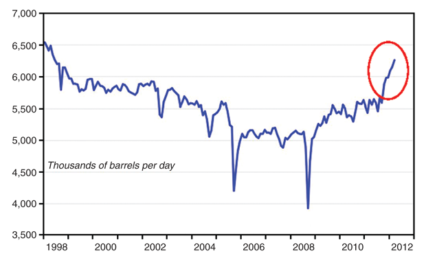
Courtesy: Murray Grigg, Kerogen Resources
The success seen in stimulating these unconventional sources of oil has been truly astounding. Reservoirs such as the Bakken and Eagle Ford have taken over the top two spots in U.S. productivity, while the venerable Permian Basin is seeing a massive resurgence, all driven by this combination of hydraulic fracturing and horizontal drilling. Figure 2 shows the very strong growth in U.S. oil production as a result of this technical success. As with natural gas supply, operators have dramatically reversed a long downward trend of annual domestic oil production.
Proppant Selection
The earliest fracturing proppants were whatever sand source was nearest the well to be fractured. Almost every type of sand has been employed, including river sand, beach sand and quarried sand. More unusual propping agents such as plastic and glass beads, walnut and pistachio shells, and even steel ball bearings also have been used!
The most readily available and cheapest supply of sand has been the “brown,” or non-API sand. Generally, brown sand has not been used in highly productive reservoirs because of its angularity, lack of uniformity, weakness and inclusions. API-specified white sand is a better choice where lower fracture conductivity potentially can limit production as a result of its better sorting, roundness and strength.
In 1978, Claude E. Cooke Jr., an engineer with Exxon Upstream Research, patented the first ceramic proppant with his invention of sintered bauxite (U.S. Patent 4,068,718). By their nature, man-made ceramic proppants are very round, very smooth and very strong.
Initially, ceramic proppants were used primarily on deeper, higher-pressured wells because of their superior strength or crush-resistance. Eventually, ceramic proppants also became known for improved conductivity as a result of their smoothness, or low “beta factor.” Consequently, ceramics now are valued in even shallower wells for their conductivity enhancement.
Ceramic proppant development did not stop there. After the first high-strength products (bauxite), came intermediate and lightweight ceramic proppants.
The global proppant market is likely more than 5 billion pounds of proppant consisting of everything from brown sand to white sand, lightweight to intermediate and heavyweight ceramics, and almost all of these products also are available with resin coating. The trend in proppant sizing in unconventional gas wells had been toward smaller proppants in the hope that more of the proppant could be placed farther into the reservoir. With the shift back toward oily reservoirs, the need for higher proppant conductivity to move liquids at high rates has caused a shift back toward larger proppant sizes.
Today, at least one company is working with nanotechnology in an effort to make proppant both lighter and stronger. As one long-time proppant industry expert often says, “The ideal proppant is one that has the specific gravity of water, the strength of iron, and is cheaper than dirt!”
Frac Chemicals
The earliest frac jobs contained few or no chemical additives, other than perhaps some biocide. As fracturing treatments began to evolve, the frac treatments themselves benefitted from the addition of additives such as gel breakers and friction reducers. It soon was recognized that the frac job was an ideal delivery mechanism for other additives that could improve a well’s productivity. Additives such as scale and corrosion inhibitors, surfactants, various clay stabilizers, demulsifying agents, hydrochloric acid and others began to improve well productivity and lifespan.
Beginning in 2005, it was recognized that some of the chemicals being used, while effective in boosting productivity and well longevity, could be hazardous, particularly in concentrated form. A movement began to produce greener additives to replace diesel; fluorocarbons; and benzene, toluene, ethylbenzene and xylenes (BTEX)–an effort that is still very much under way.
Several chemical scoring methods have been developed to determine the relative toxicity of various chemical compositions, and international standards such as REACH, GreenCheck and others have been established and are still evolving. Chemical reporting organizations such as FracFocus in the United States allow producers to disclose the chemicals being pumped on a well to the public and regulatory bodies, while still preserving some of the proprietary fluid constituents that differentiate one provider’s chemicals from another.
Outside of North America, the majority of fracs pumped in conventional formations utilize viscous cross-linked gel systems. Within North America, low-permeability gas reservoirs, particularly shale gas, are stimulated almost universally with water fracs. Typically, 10-40 percent of the fracturing fluid pumped into a well bore is recovered post-frac and must be handled for disposal or reuse.
Nearly every new chemical product being developed is created with the idea to be greener and more effective than the product it is replacing. It is not always easy (or cheap) to get greener or more effective, making chemical research and development an area where much time and effort is being spent by service companies and chemical providers alike.
One of the most promising areas of research is in employing nanoparticles as carrying agents, or “smart bots,” to ferry various chemical agents into and out of the reservoir. Their small size allows for better mobility through the fracture and the reservoir, which can aid in fracture fluid flow back, formation damage mitigation, improved hydrocarbon mobility, etc.
Just as with new proppants being developed, nanoresearch shows great promise in improving hydraulic fracturing’s effectiveness and already is improving fracturing’s environmental impact and productivity in many basins. Sustainable, green chemicals such as citrus oils are used now in conjunction with nanofluids to get better production with less environmental impact. Many chemicals under development are targeted to be biodegradable, with little to no bioaccumulation.
Biocide (disinfectants) research and development is also rapidly replacing some of the most worrisome chemicals traditionally used in a frac job. By their very nature, biocides can be harmful. The move is to “design in” biospecificity, so that the biocides target only the microbes in water and only for a short time so that there is no cumulative effect on fish, wildlife or humans. These bacteria can create sour gas and have a negative effect on gel systems, so they must be controlled. Other novel ideas are being employed such as using ultraviolet light to kill bacteria, and chlorine dioxide generators and ozone to purify frac or injection water, using a similar system to what is used to treat municipal drinking water.
Water Usage, Guar
There is no doubt that water is in scarce supply in many parts of the world. The oil and gas industry should protect and use freshwater resources wisely, and recognize the “water intensity” of various industrial uses of freshwater. Because water can be scarce in one area and overly abundant in another, water availability is a distribution problem and not a scarcity problem. A typical well today can use 3 million to 8 million gallons of water during fracturing operations.
ExxonMobil Chief Executive Officer Rex Tillerson told an audience on the Council on Foreign Relations that more freshwater flows out of the mouth of the Hudson Bay in eight seconds than all of the water used in all hydraulic fracturing operations last year!
Tillerson went on to say, “If you look at the water consumption per unit of energy that is provided, shale gas development is one of the lowest water consumptions of any form of energy we can provide you. If you look at the water consumption around coal and the water consumption around a lot of other conventional sources of energy, it is much higher.”
Increasingly, in locales where it is difficult to dispose of large volumes of fluid, or where water for fracturing is scarce, produced water is filtered and reused through a combination of mechanical and chemical filtration to render it suitable for use in subsequent frac treatments, reducing trucking, disposal and future chemical costs. Some Marcellus operators are treating and reusing 90 percent or more of their total produced water volumes.
Guar has been in the news lately because of shortages of this agricultural product. Guar beans, mostly grown in India, are ground into a powder that is used as a viscosifying agent in fracture treatments.
Also widely used in food products as a thickener for items such as ice cream, guar is environmentally friendly and historically has been readily available and inexpensive. Recent shortages caused by smaller crops and the large increase in demand for use in hydraulic fracturing have created large price swings for guar, to the extent that the Indian stock exchange suspended futures trading of this commodity.
Today, many wells that would have been stimulated with a viscous gel are utilizing thinner fluids (either water fracs or less viscous gel) to reduce the incremental cost associated with guar.
Service companies and chemical manufacturers are researching synthetic alternatives that can be cost competitive if guar pricing remains at this high level. Developing cost-effective and environmentally “green” alternatives that perform as well as guar likely will take some time, and the availability of guar appeared to be improving in midsummer, with price moderation expected to follow.
Frac Diagnostics
The most common fracturing diagnostic tool employed today is treating pressure diagnostics (frac modeling). Simple 2-D frac models were initially commercialized in the 1960s, followed by 3-D models in the 1970s, and now are widely used onsite during the fracturing operations and during post-treatment analysis.
Prior to the frac treatment, various pressure diagnostics are utilized to determine formation permeability, fracture initiation pressure, fracture fluid leak-off parameters, formation stresses and other important treating parameters. These and other parameters are input into a fracture model, which predicts both fracture geometry and net treating pressure for a given design, with net pressure as a primary matching parameter.
During the treatment itself, the actual net pressures are measured and compared with the modeled pressures, with the implication that if the actual and modeled pressures match, the modeled fracture geometry must be correct. If they do not match, the model or input variables (many of which are not well known) are adjusted until the best match for pressure is obtained. That new model of geometry is then assumed to be the real frac geometry.
The main problem with this approach is one of uniqueness. Even the simplest models have many “knobs” that can be turned to adjust the model and obtain a match, so that the final solution that matches net pressures perfectly may be nonunique (numerous solutions with different geometries could accurately match the same net pressure).
There are a number of tools available to assist in measuring the created hydraulic fracture geometry. The earliest techniques, and some of the most common still employed today, are temperature logging and radioactive tracers. Temperature logging tools measure the cooling effect of the frac fluid emplaced in a warm formation to estimate the location of the majority of fracturing fluid. Radioactive tracers employ small, short-lived radioisotopes pumped along with the proppant during treatment, followed by a gamma ray logging tool to locate the area and measure isotope concentration in the near-wellbore area.
Both temperature and tracer techniques can provide precise locations of fluid and proppant injection points. Both also have the same limitation: namely, the depth of investigation, meaning that all of the fracture geometry may not be seen from the well bore. Both of these techniques require well bore intervention with a logging tool after the frac, which can be expensive in horizontal well bores. Post-frac data acquisition is beginning to shift from logging tools to distributed temperature and acoustic sensors along a temporarily- or permanently-installed fiber optic cable that eliminates the need for the logging runs.
In the 1970s, another technique began to be developed by Los Alamos and Sandia National Laboratories, utilizing seismic geophones placed down hole near the well being stimulated. The fracturing operation creates microearthquakes or microseisms (very small events generally below the threshold that can be felt at the surface), and the downhole geophone arrays can triangulate on the source of the events to develop a real time moving image of the fracture in progress.
Tiltmeters, or extremely sensitive carpenter’s levels, also have been employed for decades to measure the tiny deformations produced by a fracture’s opening. By measuring these deformations at numerous points at the surface or down hole, a reconstruction of probable fracture size and shape can be performed to provide frac geometry.
Both microseismic and tiltmeter mapping “see” the entire fracture field, but do not have the precise resolution of tracer surveys, so both techniques often are employed in an attempt to more completely image the fracture system. Generally, resolution is improved by closer proximity to the fracture and more sensors being employed.
Once the frac geometry is known through direct measurements or modeling, the frac model is used to perform “what if” scenarios to optimize the fracture treatment. What if I pump more proppant? What if I pump a less viscous fluid? What if I change the treating rate? In this way, the most optimal treatment can be designed for a specific frac stage.
What comes next for diagnostics? While much work continues to take place in developing new sensors, higher-resolution mapping and surface-based mapping arrays, the next great frontier in frac diagnostics is likely to be the marriage of direct measurements from mapping in real time with frac models, coupled to geomechanical models coupled to reservoir simulators with a feedback loop from production data, to create a global “earth model” that more accurately describes how a reservoir behaves and predicts how it might behave under injection and production operations.
Environmental Concerns
Various special interest groups, with assistance from the media, speculate that hydraulic fracturing operations can contaminate the environment and cause earthquakes. Two high-profile claims of contamination in the Marcellus Shale and Barnett Shale have since been proven incorrect, but there remains a concern that fracturing may somehow grow from deep in the earth, up into aquifers, and contaminate water with frac fluids or hydrocarbons from the reservoir. Studies have been performed utilizing microseismic and tiltmeter data from almost 20,000 fracture treatments in numerous shale basins, and there is not a single instance where significant upward growth was measured that could threaten an aquifer (Figure 3).
FIGURE 3
Frac Heights versus Aquifer Depths
(More than 2,000 Barnett Mapped Frac Treatments)
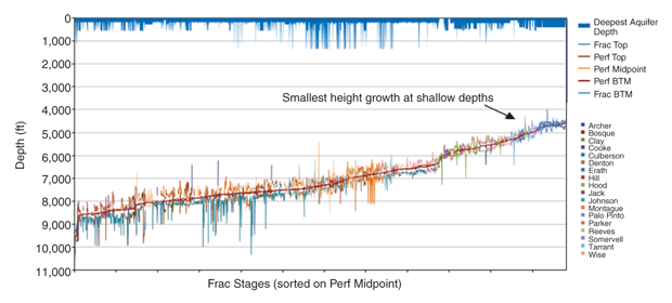
Source: SPE 145949
Additionally, data from microseismic mapping have proven useful in evaluating the seismic magnitude of the “micro” earthquakes measured during a fracture treatment. Once again, although extremely small-magnitude earthquakes are present, none mapped so far in evaluating more than 10,000 treatments have risen to the magnitude at which it would be felt at the surface. Typically, mapped microseismic events ring in at less than a -1 on a moment magnitude scale, with some of the largest recorded magnitudes at a +1. The smallest earthquake that can be felt at the surface would be a +2, if it was very shallow in the subsurface. The energy difference for one magnitude unit is 31.62, so a difference of two magnitude units equates to 1,000 times the energy.
There may be unusually unstable tectonics in some regions where a frac job could trigger a small earthquake detectable at the surface, but the scientists studying this issue have determined that fracture treatments are generally too small and too short in duration to trigger earthquakes. However, injection wells where injection volumes are large and continuous could potentially destabilize a reservoir and trigger an earthquake. Therefore, injection/disposal well locations should be chosen carefully to ensure a stable tectonic regime.
The relatively large volumes of water and sand needed for fracturing creates increasing transportation difficulties in terms of the availability of rail and truck transport, traffic congestion and additional wear and tear on road and bridge infrastructure. New ideas are being implemented such as localized water storage and distribution systems to minimize some of these problems. Also, noise, air pollution and well footprint issues are leading to discussions on moving away from diesel engines, noise suppression and barrier installation, and already have driven the move toward pad operations where multiple wells are drilled from a single surface location to minimize the footprint.
There have been no confirmed cases of hydraulic fractures themselves contaminating groundwater supplies. Of course, attention must be paid to well construction with appropriate barriers of casing and cement separating the well bore from the aquifers near the surface. Tight oil reservoirs are increasingly being exploited commercially in the United States, and they also require fracturing technology to produce economically.
If natural gas is to become the “bridge fuel” to the future while alternative/renewable sources are being developed, then hydraulic fracturing, applied in conjunction with horizontal drilling, will remain the key that unlocks these massive natural gas reserves.
As Marty McFly said, “I guess you guys aren’t ready for that yet. But your kids are gonna love it!”
Editor’s Note: The author acknowledges Claude E. Cooke Jr., the father of ceramic proppant, who now practices law at Cooke Law Firm in Conroe, Tx., and Norm Warpinski, director of technology at Pinnacle, a Halliburton Service, in Houston, for their proofing, suggestions and editing assistance.

Kevin Fisher is executive vice president of business development at Flotek Industries, where he is involved in developing and marketing green fluid chemistries to optimize the hydraulic fracturing process. He began his career with Halliburton in 1979 and served for 14 years as logging engineer, field supervisor, log analyst, U.S. sales manager, and global technical marketing manager. Fisher joined ProTechnics as director of sales and marketing in 1993 and Pinnacle in 2000, eventually serving as chief executive officer until Pinnacle was sold to Halliburton in 2008. Fisher then served as general manager of Pinnacle, a Halliburton Service, until he joined Flotek in 2011. He holds three U.S. patents related to spectral gamma ray, gravel pack density logging, and tiltmeter instrumentation. Fisher holds a B.S. in natural science/physics from Cameron University.
For other great articles about exploration, drilling, completions and production, subscribe to The American Oil & Gas Reporter and bookmark www.aogr.com.
