


Artificial Lift Advances Address Challenges, Trends In Gas Well Deliquification
By James F. Lea and Cleon L. Dunham
AUSTIN, TX.–The technologies for addressing problems with natural gas well liquid loading continue to advance, and these advancements have been pursued to address many of the trends and new challenges that face the gas production industry in 2009.
Based on the most recent available data, there are more than 450,000 natural gas wells in the United States, up from 300,000 wells a decade ago. In total, these wells produce ±50 billion cubic feet a day, and the average production output per well is 110 Mcf a day. That means the typical U.S. gas well produces well below the “critical rate” that is needed to keep wells unloaded, which averages about 300 Mcf a day at a wellhead pressure of 100 psi. Consequently, 90 percent of all gas wells now on production experience liquid loading problems. For effective gas production without the hindrance of liquid loading, these wells need to be deliquified by some form of artificial lift.
In addition to the general challenge of needing to remove liquids from 400,000-plus gas wells, operators are encountering a number of other trends and challenges associated with gas well deliquification/artificial lift. These include:
- Economics;
- Deep wells;
- Long perforated intervals;
- Horizontal completions;
- Tight reservoirs;
- Coalbed methane wells;
- Wells with subsurface safety valves;
- Wells with tubing corrosion problems; and
- Automation systems.
Economic Pressures
Foremost among the challenges are new economic realities driven by gas prices that have essentially been halved on the New York Mercantile Exchange since late last summer. Although prices had recovered to the $4.30 range by mid-May, the general downward pressure on gas prices throughout the winter heating season has placed pressures on capital investments for artificial lift systems as well as on operating costs.
With operating companies working to reduce both capital and operating costs, the service and supply companies also are working to reduce costs to meet their customers’ needs. An example of such initiatives includes combining pumping systems with wellhead compression to try to make the best of both worlds. While this can be an effective method of deliquification, it may not always be the most economical.
Continuous plungers are commonly used early in the life of loaded wells, followed by conventional plungers. However, once conventional plungers are no longer effective, there are a number of ways to continue to utilize plunger lift before moving to a more expensive pumping or gas-lift system. These include progressive or staged plungers, plunger-enhanced chamber lift (a method of intermittently lifting a plunger above a standing valve), and using compression to lower wellhead pressure and/or to inject gas into the casing annulus.
A new hydraulic reciprocating pump has been introduced that can fit into 4½-inch casing and is being operated at progressively deeper depths. Gas lifting of gas wells is also becoming more common. Gas-lift systems can handle sand and well bore deviation, and lower liquid production rates that cause trouble with pumping systems. Methods include gas-lift with valves and a packer above the perforations (the conventional approach), designs to allow injection below the packer and into the perforated interval, and gas circulation where liquids are removed from the well first and then lower-pressure gas is injected down the casing annulus and around the end of the tubing.
In addition, there is a method for using a dead string to increase the velocity in the perforations, while simultaneously using surfactants to lower the required critical velocity. It has variations for flowing wells, and for plunger lift. Many more approaches to improve the economics of gas well deliquification are highlighted in Table 1.
Deep Wells, Long Intervals
While the average depth of gas wells in the Unites States is about 5,500 feet–with more than half (approximately 265,000 wells) shallower than 6,000 feet–there are some 65,000 wells that are more than 9,000 feet deep. These deep wells offer special challenges to lift often relatively low liquid rates from at or below the perforations. Another challenge is that many of these wells are in remote locations where there is no electrical power infrastructure.
Many of these wells are “late” in their life cycles and reservoir pressures are often low. While inflow performance may have decreased and remaining reserves are limited, there are usually enough remaining reserves to justify methods to recover them. Plungers and other “conventional” means of artificial lift may no longer be viable, and new methods are needed to lift relatively small volumes of liquid from deep wells, often without available electrical power.
Methods are being explored to use pumps of various designs to address this problem. For very deep wells, pumps (other than some conventional hydraulic systems) may lose effectiveness. Gas-lift and gas circulation may sometimes be used. Also, plungers sometimes can be used in deep wells as long as the well has few solids and is not deviated more than ±60 degrees.
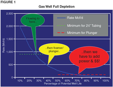
Figure 1 shows an example production curve for achieving greater depletion potential and extending well life by adding artificial lift.
Many gas wells are completed with long perforated intervals. This presents challenges on where to land the end of the tubing, and how to deliquify the lower zones without placing back pressure on, or risking back flow into, the upper zones.
Some perforated intervals may be thousands of feet long, often encompassing multiple reservoirs with varying pressures, porosities, permeabilities, liquid contents and gas compositions.
In general, the best approach is to land the tubing as deep as possible, below most or all of the perforated intervals. If the end of the tubing is high in the perforated interval, liquid can accumulate below the tubing but above many of the perforations, thereby inhibiting gas inflow from these lower zones.
Another common approach is to place the end of the tubing below the most productive gas zone, as determined by a production logging tool. The idea here is to maximize production from the “good” zone(s) while realizing that the poorer zone(s) will not produce much gas anyway.
Success in lifting these wells has been achieved with pumps, if they can be landed deep in the well and keep the well “pumped off,” and with gas-lift, where the gas is injected deep in the zone and at a rate sufficient to keep the overall gas flow rate above the critical velocity.
Success has been reported by Schlumberger with its PerfLift™ system, Weatherford with its XtraLift™ system, and Marathon with its “below packer” gas-lift system. These are designed to provide gas lift from deep in a zone, below a packer if necessary, and in or below the perforated interval.
Another method uses a dead string and surfactants to create flow above the critical rate in the perforated interval. Even with conventional plungers, it is sometimes possible to set the end of tubing 75 percent of the way down in the perforated interval.
Horizontal Completions
Many gas wells have horizontal completions, with the goal being to contact more of the reservoir than with a vertical well. In fact, operators now are drilling almost exclusively horizontally in many shale gas plays, including 4,000-foot and longer laterals in the Barnett, Fayetteville, Marcellus and Haynesville shales.
However, horizontal wells present challenges in installing artificial lift equipment in the lateral sections and operating the wells to avoid serious gas/liquid slugging in the horizontal sections.
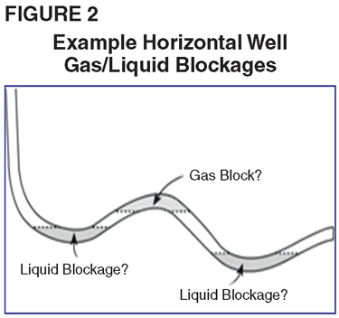
Horizontal, of course, does not mean that the well bore in the “horizontal” section is straight or constant. The inclination and azimuth may vary considerably along the horizontal path. The liquid/gas gravities can vary accordingly (Figure 2), which may affect flow velocities, fluid collection and flow regimes.
There may be fracture ports, liners, and other internal diameter changes, all of which can introduce friction, turbulence and flow restrictions.
Wells can have either cased or open-hole completions, with further issues of friction, corrosion and further flow restrictions. In addition, there may be sand production and accumulation that also can introduce friction, turbulence and flow restrictions.
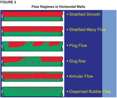
Flow regimes in horizontal wells can be very complicated (Figure 3). Flow is affected by multiple variables and changes with angle, rate, gas/fluid densities, and temperature. Multiple flow patterns or regimes exist across all parts of the well (horizontal, inclined or deviated, and vertical).
Plungers may not run to the end of the well bore, thereby leaving some liquid in the bore hole unlifted. There has been some success in horizontals with gas-lift and low-rate electrical submersible pumps. Both can be installed below the “knee” of the well and into the horizontal section. Gas-lift is commonly used in horizontal wells because of gas separation problems with pumps and because the technique can handle hot and sandy wells.
There have been successful applications of electrical submersible pumps using an upturned shroud over the intake. There is also a focus on using sucker rod pumping in horizontal wells as long as the pump can be landed in a relatively vertical section and care is taken to achieve gas separation. Setting above the kickoff point is similar to using sucker rod systems in vertical wells. There is evidence that setting in the horizontal may reduce run life by 40 percent and setting in the curved section may reduce lift capacity by 70 percent. Also, horizontal wells present special problems for pumps since they cannot be set below the perforations to separate gas.
Tight, CBM Reservoirs
Many gas wells are being completed in tight (ultralow-permeability) sand and shale reservoirs, spurring growth in horizontal drilling activity as well as hydraulic fracturing services. Most shale and tight sand reservoirs must be fractured to obtain economic gas inflow from the rock formation. This often takes the form of massive multistage frac jobs that pump large volumes of proppant down hole. To achieve optimal flow rates and avoid problems after a well is placed on production, the frac sand that does not lodge in the formation must be recovered.
The flow back and recovery of fracture proppants causes difficult problems when using pumps. If properly designed, pumps can produce some solids. However, the production rate has to be high enough to flush the solids out of the well and keep them from settling back into the pump. Therefore, gas-lift or some other lift method such as jet pumping may be required if solids production is significant.
The other major focal point of unconventional gas activity is coalbed methane. Although CBM wells generally do not have the reserves or high production rates associated with shale and tight sands reservoirs, many wells continue to be drilled into coal formations to recover the methane trapped within the coal matrix. There are special challenges to recover coal fines and to address liquid recovery rates that may range from large early in the well’s life as a coal seam dewaters to minimal later in life.
Even with the existence of coalbed fines, sucker rod pumps are still frequently used. If solids are more prolific, progressing cavity pumps often are applied. As in shale and tight sands wells, the flow back of frac can be a significant issue. In fact, proppant flow back often causes more problems than the coal fines themselves. And, of course, the usual gas separation problems remain for CBM pumped wells.
Gas-lift is usually not as attractive for CBM wells as it is for wells with larger liquid flow rates, since it may not achieve lower bottom-hole pressures. However, gas-lift may be required for some problematic wells.
Subsurface Safety Valves
Governmental regulations require most offshore and more and more onshore wells to use subsurface safety valves. Advancements are being made in using plungers and chemical systems for producing below an SSSV.
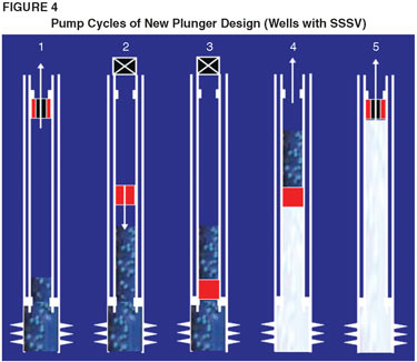
A new plunger design travels from below the SSSV to the bottom of the well and returns. A complete pump cycle (Figure 4) includes five distinct stages:
- Cycle 1, liquid loading (the plunger hangs in open position under the SSSV, liquid in the liner and tubing builds up, and the flow rate declines);
- Cycle 2, shut-in (the well automatically shuts in and the plunger falls);
- Cycle 3, Shut-in build-up (the plunger reaches bottom and closes, followed by a short build-up time);
- Cycle 4, unloading/plunger travel (the well automatically opens and delta pressure lifts the plunger and the liquids in a closed position); and
- Cycle 5, flowing well (the plunger hangs in the open position under the SSSV).
Another new method permits chemical injection below an SSSV while maintaining the safety valve’s integrity by using a capillary string and a special tool to bypass the SSSV.
Tubing Corrosion
A surprising number of wells have existing or pending holes in the tubing caused by corrosion. The first task is to detect the corrosion and existing or pending holes so the problem can be addressed.
Internal tubing corrosion, which can lead to holes, is difficult to detect, but can have significant economic implications. If there is a hole, the tubing will most likely need to be replaced. If there is corrosion but no hole has developed, it may be possible to prevent further damage by taking the appropriate corrective action.
Corrosion in the tubing strings of flowing or artificially lifted gas wells is a common problem, yet well problems caused by a hole or corrosion in the tubing string often are misdiagnosed or overlooked. Problems occur slowly, as corrosion gradually creates a hole, which increases in size over time.
The relatively high cost of using wireline to set a standing valve and pressure test the tubing may be avoided. Also, many operators are reluctant to use wireline tools since it requires that the well be shut in. And there is always some risk when running wireline tools in a well. If there is corrosion, they may become stuck.
An alternative to detect corrosion or a hole in the tubing wall is to use an acoustic fluid level instrument. It provides a quick, low-cost method to troubleshoot a gas well to identify potential problems (Figure 5).
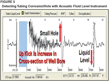
The well still needs to be shut in for a short time, but no equipment needs to be run in the well. The acoustic survey detects changes in the cross-section of the tubing, which can be interpreted to detect the build up of corrosion products and/or holes in the tubing string.
Production Automation
A final major trend impacting gas well deliquification and production is automated operations. With pressures on staffing resources and costs, more and more focus is being placed on automation to augment gas well operation, control, maintenance and optimization.
Many wells are being drilled horizontally from multiwell pads, particularly in environmentally sensitive regions such as the Rocky Mountains. This has obvious advantages for reducing the “footprint” of wells and equipment, allowing combinations and economies of scale of surface equipment as well as the use of automation systems that can address several wells with one set of automation hardware and software.
There is much interest in automation as a means to improve gas well operation, control, surveillance, problem detection and diagnosis, design, and optimization. It also can be a significant contributor to reducing operating costs. Some highly compelling benefits can arise from applying automation to gas well deliquification operations, economic and otherwise.
One evolving approach for automating gas wells and associated facilities is using wireless communications to transmit information between the instruments, remote terminal units, and the host automation systems. This has the obvious advantages of reducing installation costs (no trenching for communication cables) and lowering maintenance costs (no cables being cut).
With at least 15 methods of artificial lift now being used to deliquify gas wells, and several more combinations and permutations, operators are often in a quandary concerning exactly what method or system to use. To this end, the Artificial Lift Research & Development Council, a nonprofit organization that promotes the development and sharing of recommended practices and information in all aspects of artificial lift, is coordinating a team of industry experts to develop a set of recommended practices to assist operators in selecting the most appropriate artificial lift technique for their gas well deliquification applications. For more information, see the “Recommended Practices, Gas Well Deliquification” section at http://www.alrdc.com.
Editor’s Note: Some of the information in the preceding article was adapted from technical presentations at the 2009 Gas Well Deliquification Workshop, held Feb. 23-26 in Denver. The co-authors acknowledge the following presenters for their topical contributions:
- Combining a new downhole tool and wellhead compression to dewater gas wells, by Larry Perry and David Lewis, Cyclone Production Tools; and Ted Garner, COMPRESSCO Field Services;
- Using pressure-activated chamber technology as an artificial lift system for CBM wells, by Leslie Lam, Black Hills Exploration; Ryan Davis, Merrion Oil & Gas; Mark Turland, ProActive Pumping Solutions; and Jim Wetzel, Nojak Pumping Solutions;
- Deviated plungers in low-rate horizontal wells, by Alex Rodriguez, BP;
- Sucker rod lifting horizontal and highly deviated gas wells, by Norm Hein Jr., Oil & Gas Optimization Specialists;
- Plunger lift SCSSSV applications by William Hearn, Weatherford; and Stathis Kitsios, Sachin Shinde, Dick Klompsma and Ewout Biezen, Shell NAM;
- Completion techniques to minimize liquid loading, by Jeff Bolding, BJ Services;
- Corrosion in gas well tubing, by Rick Nadkrynechny, T-Ram, Canada; and Lynn Rowlan, Echometer;
- Automating plunger lift pad sites, by John Green, ABB Totalflow; and Lee Sargent, Anadarko Petroleum; and
- Wireless communication to plunger lifted wells, by Jim Gardner, FreeWave Technologies.
For more detailed information on workshop presentations, visit http://www.alrdc.com.

JAMES F. LEA, Ph.D., is teaching courses in all areas of artificial lift, gas well dewatering, and nodal analysis through Petroskills, and is engaged in consulting work. He chaired the petroleum engineering department at Texas Tech University for seven years and was formerly the team leader of production optimization and artificial lift at amoco EPTG, where he was employed for 21 years. As chairman of the board of the Artificial Lift Research & Development Council, Lea was instrumental in founding the annual Gas Well Deliquification Workshop. He is co-author of “Gas Well Deliquification” (2nd Edition), published by Elsevier, author of a chapter on artificial lift completions (Chapter 16) of “Petroleum Well Construction,” and wrote the chapter on artificial lift selection in the new Society of Petroleum Engineers Production Handbook. Lea is a past recipient of SPE’s International Production Award, and the Southwestern Petroleum Short Course’s J.C. Slonneger Award for outstanding contributions to artificial lift.

CLEON DUNHAM is president of Oilfield Automation Consulting, providing consulting in oil and gas field automation and artificial lift. He is also president and chief executive officer of the Artificial Lift Research & Development Council. Dunham retired in 2000 after 36 years of service with Shell Oil Company, where he focused primarily on production automation and artificial lift. Much of his automation experience was directed at monitoring, controlling and optimizing artificial lift operations. He spent his last five years at Shell International Exploration & Production, where he was production automation coordinator for Shell’s worldwide producing operations. Dunham has written extensively and has taught numerous industry courses on artificial lift and automation.
For other great articles about exploration, drilling, completions and production, subscribe to The American Oil & Gas Reporter and bookmark www.aogr.com.