


Approach Uses Tray Design To Optimize Treating Shale Gas Containing H2S and CO2
By Ralph H. Weiland and Nathan A. Hatcher
HOUSTON–Natural gas supply from shales has expanded dramatically over the past decade, growing from a starting point of essentially zero to account for more than one-third of U.S. production. Within 20 years, shale gas is forecast to represent more than half of total domestic production.
By any measure, shale represents a vast new source of natural gas and natural gas liquids. Although some wells produce pipeline-quality sweet gas that does not require treatment, many shales produce gas with carbon dioxide and hydrogen sulfide. This can present unique treating challenges, particularly when H2S-to-CO2 ratios are low. Moreover, there can be considerable variation from play to play and even from well to well within the same play.
While shale gases typically do not have high H2S contents, shale gas often contains tens or hundreds of parts per million of hydrogen sulfide with wide variability in CO2. The Barnett Shale in the Fort Worth Basin is an example. H2S is also present in other shale plays, including the Haynesville and Eagle Ford. The Antrim Shale contains up to 30 percent CO2. Also in the Antrim, as well as shales such as the New Albany, underlying sour Devonian formations may communicate with and contaminate gas.
Although the focus in the Marcellus Shale is on recovering NGLs, the residual methane itself is an enormous energy source regardless of the play. After removing the NGLs, there are many situations in which shale gas may still need to be treated to pipeline specifications for sulfur content and often for CO2.
One of the frequent challenges in treating shale gases is the very low H2S-to-CO2 ratios and the desire to meet, but not exceed, pipeline specifications for CO2 content. This means that only a small flow of solvent is needed to treat a large volume of gas, and selectivity for hydrogen sulfide often must be maximized. In terms of both cost and effectiveness, the traditional solvent of choice for H2S removal and CO2 rejection in gas treating plants is N-methyldiethanolamine (MDEA). The trick, however, is to reduce H2S content from a few hundreds parts per million to pipeline specifications without simultaneously removing too much CO2.
New Treating Strategy
To help meet this objective, a relatively new treating strategy is being deployed that uses tray designs specifically tailored to treating shale gas to maximize H2S absorption while minimizing CO2 removal. The key to profitably implementing this strategy is understanding that trays have radically different mass transfer performance characteristics when operating hydraulically in a “froth” versus a “spray” regime.
A critical element is the availability of a true mass and heat transfer simulation capability. A model grounded in solid engineering science is crucial because the selectivity issue is intimately tied to the separation taking place from a mass transfer rate perspective and how the hydraulic operating regime affects transfer rates. “Ideal” stages are incapable of properly dealing with this issue, because an ideal or equilibrium stage is oblivious to the effect of hydraulics on mass transfer and cannot distinguish what is actually in the column.
The hydrogen sulfide absorption process is controlled by resistance to mass transfer in the gas phase, while carbon dioxide absorption is controlled by liquid-phase-resistance. In practical terms, whatever can be done to lower gas-phase resistance and increase liquid-phase resistance should improve H2S pickup and increase CO2 rejection. Of course, it is also important to select a solvent that is inherently highly selective for H2S. MDEA is the quintessential selective amine because it is tertiary and does not react with CO2. The main CO2 reaction is hydrolysis, with the amine acting merely as a large “sink” for the protons liberated by hydrolysis.
Although MDEA may slightly catalyze the CO2 hydrolysis reaction, CO2 absorption into MDEA occurs at more or less the same rate as it does into water. In both cases, the real solvent is effectively water. MDEA is not a direct participant; its purpose is to increase the solvent’s total capacity for CO2 (and H2S).
Because the process is controlled by mass transfer rate (liquid-phase resistance), any slight catalysis of the hydrolysis reaction will be negated by increased mass transfer resistance from the higher amine solution viscosity. The reaction kinetics are too slow to matter, and CO2 and H2S absorption rates are controlled strictly by the mass transfer characteristics of the specific tower internals (trays or packing) operating under the specific hydraulic conditions imposed.
Tray Hydraulics
Beyond pressure drop and flooding calculations, gas treating engineers traditionally have not given much thought to hydraulic flows on trays. However, the structure of the “biphase” vapor/liquid mixture on a tray can have a profound effect on selectivity. In conventional gas treating, the liquid and vapor mass flow rates normally are not radically different, depending on the amount of acid gas to be removed. The biphase is a froth, and the vapor is dispersed within a continuous liquid. But as the acid gas content of the raw gas decreases and only a few hundreds ppm of H2S are to be removed (as is common in shale gas treating), removal can be achieved using a very low liquid flow rate relative to gas flow.
In this case, the liquid flow is so low that it becomes impossible to maintain a reasonable liquid depth on the tray, even with deep (high) weirs. The vapor shatters the liquid into droplets, with the liquid becoming the dispersed phase and the vapor the continuous phase. At that point, the tray is operating in the spray regime. In aqueous systems such as amine solutions, the droplets typically are about one millimeter in diameter.
In the froth regime, the gas passes through the tray perforations and enters the liquid as high-velocity jets and large bubbles, resulting in tremendous liquid agitation. Liquid agitation causes high liquid-phase mass transfer coefficients, but gas agitation is modest, especially near the gas/liquid interface, where most of the mass transfer resistance to H2S absorption resides. This results in fairly moderate gas-phase mass transfer coefficient values.
The spray regime is quite different. The liquid droplets are so small that they are almost rigid and barely agitated at all. The mass transfer resistance “film” is the entire drop, there is little or no internal convection, and components move into the interior by purely molecular diffusion. The implication is very small liquid-side mass transfer coefficients. The gas, on the other hand, streams past the drops at high Reynolds numbers (on the order of 500 or more), and the gas flow is turbulent over much of the drop surface. This means reduced gas-side resistance to mass transfer.
Spray Regime
Bearing in mind that CO2 and H2S absorption are controlled by liquid-and gas-side resistances, respectively, the spray regime should be conducive to much better H2S absorption and greatly reduced CO2 removal. In short, trays operating in the spray regime should give better selectivity. Unfortunately, the spray regime has acquired a very bad reputation for causing reduced column hydraulic capacity (early flood)–mostly in distillation–to the extent that spray regime operation is avoided studiously. But is this reputation deserved, and what is the reason for the observed premature flood?
A quick calculation shows that for water-like drops of this size in a gas stream up to several thousand psi, the free-fall velocity of the drops is significantly higher than the gas velocity, leaving a froth at flood. In other words, the spray-regime gas velocity at flood should be even higher than the flood velocity in the froth regime, and the spray regime should flood later, not earlier. But there is an unspoken assumption that the downcomers are sealed and all vapor passes through the tray openings, not up the downcomers. Many high-capacity trays are designed with dynamic seals to operate at relatively high liquid flows, and sometimes tray designers inadvertantly fail to make allowances for lower weir liquid loads.
A low weir liquid load is completely incapable of dynamically sealing a downcomer, resulting in high velocity gas flowing up the downcomers and causing massive entrainment of liquid to the tray above (i.e., premature flood). Downcomers for low weir liquid loads should be sealed using mechanical seal pans to hydrostatically prevent gas from flowing up them. Once this is done, a column can very satisfactorily be operated in the spray regime. The secret to successful spray-regime tray operation is proper tray design and attention to downcomer seals.
A multiple-pass tray typically is used to shorten the flow path length, and/or accommodate weir liquid loads that are too high for a single-pass tray and a single downcomer. Most downcomers do not adequately handle weir flows in excess of 225 gallons per minute/foot (gpm/foot), and a two-pass tray will cut that load nearly in half.
However, a third reason for using a multiple-pass tray is to force hydraulics into the spray regime to take advantage of the effect on selectivity. The transition from froth to spray is gradual and begins at a weir liquid load of about 65 gpm/foot. The amount of spray is significant by the time the weir load is reduced to 30-40 gpm/foot, and the tray is well into the spray regime below 30 gpm/foot. Therefore, if a one-pass tray is operating at 60 gpm/foot weir load, going to two passes will throw the operation into the spray regime, and huge selectivity benefits will occur.
Barnett Shale Plant
An example of the magnitude of this effect is illustrated by an application at a plant built to process gas from the Barnett Shale. This plant was designed with a daily capacity to treat 330 million cubic feet of gas containing 750 ppm H2S and 2.5 percent CO2 at 960 psi to pipeline quality (4.0 ppm H2S by volume and less than 2.0 percent CO2). The absorber was designed with 12 single-pass valve trays using an equilibrium-stage simulator with assumed tray efficiencies. From its startup in mid-2009, the plant consistently failed to produce on-spec gas at more than 60 percent of the nameplate rate, even with reboiler and circulation pumps running at full capacity.
Spiking the generic MDEA solvent with a stripping promoter allowed it to reach 73 percent of capacity, but the internals were inadequate to increase beyond this limit. Revamping the tower, perhaps even installing a taller column, was required.
Numerous cases were run using a genuine mass transfer rate-based amine simulator to determine possible courses of action to achieve the required specifications in the treated gas. Absorber tray count, solvent rate, amine strength, and gas and solvent temperature were all varied. Consideration also was given to tray type and design, using structured packing–and even a combination of packing and trays in the same column–to achieve the nameplate rate.
Higher solvent circulation rates and a more aggressively reboiled regenerator would improve H2S treating, but worsen the already too-high CO2 removal. The solvent contained 50 weight percent MDEA with a stripping promoter, making it impossible to meaningfully raise amine strength. Moreover, hot oil flow to the regenerator reboiler and the circulation rate through the unit were already at equipment limits.
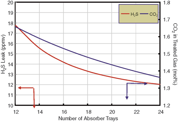
FIGURE 1
Single-Pass Absorber Tray Count versus
H2S and CO2 Content
Simulation indicated that raw gas temperature was one of the most influential parameters (solvent temperature had a much lesser effect because of the plant’s high gas-to-liquid ratio). However, significantly reducing the gas temperature would have required a large gas heat exchanger, and even the lowest realistic gas temperature was insufficient to allow treating at the designed capacity. The only approach that made sense was completely redesigning the trays and absorber tower. The focus shifted to the tower internals, with a goal of enabling operation with generic MDEA without additives.
As shown in Figure 1, adding single-pass trays would reduce the H2S leak, but not enough to meet specifications at the designed gas flow. The problem with the absorber is that the more trays there are, the more CO2 is removed. The solvent removes the wrong component (CO2) at the expense of the noncompliant component (H2S). No matter how many trays are used in the absorber, generic MDEA cannot allow the gas specification to be met at design rates.
Using a stripping promoter would allow 20 trays to meet the H2S specification (assuming 20 trays could be shoehorned into the space available in a column designed for only 12 trays), but carbon dioxide removal would be grossly excessive, leaving only 1.3 percent CO2 in the treated gas. However, with the weir load for this plant at 65 gpm/foot–right on the edge of the spray regime–it was recognized that two-pass trays offered the possibility of higher selectivity.
FIGURE 2
Processing Design Gas Rate at Reduced Circulation (20 Two-Pass Trays with 50 wt% Generic MDEA)
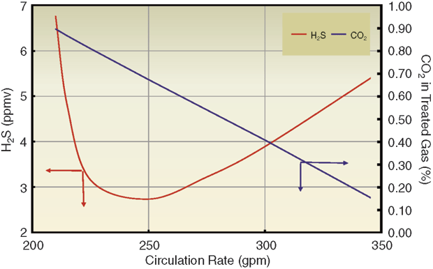
Although single-pass trays are perfectly adequate in terms of hydraulic capacity, the simulation indicated that two-pass trays would reduce the weir liquid load from 65 to 40 gpm/foot, pushing the process into the spray regime and offering significant benefits to both H2S removal and CO2 slip. The already low rich solution loadings suggested that the solvent had more capacity than was being used. Consequently, reducing the solvent rate to below the plant limit would make the weir load even lower, further enhancing H2S removal and CO2 slip.
In addition, the reboiler energy input would act on less solvent, although there was unlikely to be real benefit from a lower solvent flow per unit of reboiler duty, since the same amount of absorbed gas would still have to be stripped. Figure 2 shows simulated treating results for a 20-tray absorber containing two-pass trays as a function of solvent rate. The mass transfer rate-based model shows there is an optimal solvent circulation rate around 250 gallons a minute (70 percent of the pump capacity) that will produce gas a little below 4 ppm H2S by volume with 2.0 percent CO2 content.
Keys to Success
The keys to successfully improving treating in this Barnett Shale plant were to use mass transfer rate-based simulation together with knowledge of how such tower internal details as the number of tray passes can affect mass transfer. This kind of technical sophistication in the simulator has allowed the simulation model to be converted into a “virtual plant.” An absorber completely unable to meet the gas specification no matter how many trays it contains can be made to work using the right tray design.
And if the risk of a design this tight in meeting the H2S specification is unacceptable, the 4 ppm target can be achieved easily (<0.5 ppm) with a stripping promoter. Shale gas can be very challenging to treat. However, mass transfer rate-based simulation and appropriately specified and designed tower internals can make shale gas treating no harder than treating any other gas. Without both, however, treating low-H2S shale gas becomes simply a matter of guessing.
With inadequate modeling tools, shale gas treating units can be challenging to simulate and build with reasonable confidence in meeting performance guarantees. The complication lies in the very low H2S content of shale gases, which leads to low liquid rates being used to treat large gas volumes. As this case study demonstrates, a critical and essential element in reliable tower design for shale gas treating is a solid mass transfer rate-based simulator because the tray hydraulic operating regime profoundly affects mass transfer, and therefore, the very separation process itself.
Under conditions that seem fairly common in shale gas treating, trays often have to be operated in the spray regime, where care must be taken to ensure downcomer bottoms remain positively sealed. However, the potential advantage from forcing operations into the spray region is that the more spray-like the biphase, the greater the selectivity enhancement.
Entrainment rates and tray capacity do not have to be negatively affected by the sprays that accompany low-weir liquid loads, as long as downcomers are positively sealed, preferably with recessed seal pans. Multiple-pass trays are a powerful, but unappreciated strategy that can be brought to bear in amine unit design to meet the unique treating challenges presented by shales and other gases requiring small liquid flows to treat large gas volumes.

RALPH H. WEILAND is president of Houston-based Optimized Gas Treating Inc. He began working in gas treating in 1965 and has been active in basic and applied research in the field ever since. He taught chemical engineering for 30 years at universities in Canada, Australia and the United States, and directed graduate research in gas treating. Weiland led the development of an earlier version of a mass transfer rate-based model for amine columns and commercialized its concepts in the GasPlant-Plus™ software package, now part of WinSim™. In addition to developing the Windows-based ProTreat™ process simulation package with Optimized Gas Treating, Weiland served for 10 years at Koch-Glitsch LP in Dallas, primarily involved in tray development. He holds a B.S., an M.S., and a Ph.D. in chemical engineering from the University of Toronto, and spent two years as a post-doctoral fellow in applied mathematics at the University of Western Australia.

NATHAN A. HATCHER joined Optimized Gas Treating Inc. as vice president of technology development in 2009. He has been involved with gas treating and sulfur recovery for most of his 17-year career. He spent his early career designing, evaluating, training and starting gas treating and sulfur recovery technologies with Black & Veatch Pritchard Inc. Hatcher then joined ConocoPhillips Inc., where he served as treating and sulfur processing best practices network coordination lead. During this time, he became an expert user of Optimized Gas Treating’s ProTreat technology, providing technical support for refinery treating and sulfur recovery operations. A member of the Amine Best Practices Group, he has spent nearly his entire career in amine treating and sulfur recovery, most recently with Trimeric Corporation, and has extensive experience in the practical application of process simulation to operations, troubleshooting and training. He holds a B.S. in chemical engineering from the University of Kansas.
For other great articles about exploration, drilling, completions and production, subscribe to The American Oil & Gas Reporter and bookmark www.aogr.com.