


PIT Airport Project Optimizes Horizontal Drilling Results
By Kevin Gorr, Ryan Coffman, Luke Beebe, Denise Azuaga Livingston, Drew Andes and McKenna Czerneski
CANONSBURG, PA.–More than 240 flights carrying some 22,000 passengers move through the runways and concourses of the Pittsburgh International Airport every day. But below the PIT complex are the prolific Marcellus and Upper Devonian shales, and potentially, the deep dry Utica shales that underlie western Pennsylvania. In 2013, CONSOL Energy entered a partnership with the Allegheny County Airport Authority (ACAA) to develop natural gas reserves beneath 9,263 acres on PIT grounds. A dry Utica test well has been approved by federal, state and local authorities, and will replace a Marcellus well in the 47-well PIT development plan.
The initial plan calls for six horizontal well pads. Dictated by topographical and environmental features, and the need to avoid obstructing growth of airport surface facilities, the unique location requires constructing complex wellbore geometries with high buildup curves and long laterals.
While longer laterals and complex geometries optimize lease development, improve well economics and increase reserves recovery, they create challenges related to the surface location, lease boundaries, build sections, landing points, and torque and drag management.
CONSOL Energy launched drilling operations on the six-well Pad ACAA-2 in late 2014. It then initiated a multidisciplinary team effort to apply lessons learned on Pad 2 to improve drilling performance on the eight-well Pad 1. A key part of the team’s solution was incorporating an advanced high buildup rate rotary steerable system (HBRSS) to optimize well profiles with high buildup rates (BURs), to efficiently drill long laterals while remaining in zone, and to drill the vertical, tangent and lateral sections in a single run.
The combination of HBRSS technology with a detailed data communications workflow and effective best practices for bit and bottom-hole assembly design, drilling parameter optimization, and reservoir navigation techniques resulted in optimized drilling times, reduced operational costs, financial predictability, and consistency on Pad 1 wells. In fact, half the wells achieved record footage rates consistently greater than one mile within 24 hours, and the majority of the laterals remained in the target zone 100 percent of the time.
The team of drilling, geoscience, and reservoir navigation experts collaborated to address the engineering challenges on Pad 1 and design an extensive plan that focused on two main goals:
- Achieving the best reservoir exposure for optimal production from the Middle Devonian Marcellus as well as targeted Upper Devonian formations; and
- Maximizing drilling efficiency and consistency, including increasing penetration rates, eliminating drilling laterals out of zone, and drilling the vertical, curve and lateral sections in one BHA run.
Pad Design And Spacing
As shown in Figure 1, both Pad 1 (blue) and Pad 2 (red) were designed with negative vertical sections and long laterals, but Pad 1 wells are characterized by longer laterals with optimized spacing to enable developing two formations from the offset Pad 2 wells. The lateral lengths of the eight Pad 1 wells averaged 9,700 feet, and the curve sections had BURs up to 10 degrees per 100 feet. HBRSS technology consistently achieved the desired BURs in the 8¾-inch curve section to land at the predetermined landing point and then drill the lateral to total depth using near-bit inclination and gamma ray readings to stay within the target zone.
FIGURE 1
Spider Plot of Pad 1 (Blue) and Offset Pad 2 (Red)
At PIT Airport Project
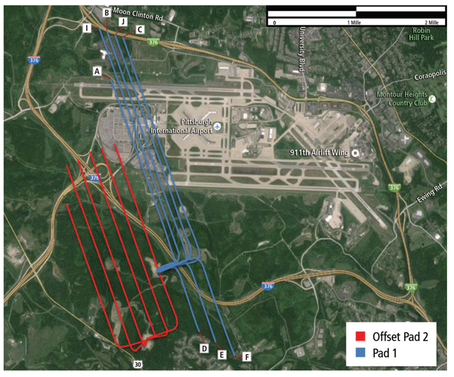
Source: Google Earth and well surveys
Initially, the optimization process centered on offset data analysis from Pad 2 to determine opportunities for improvement, focusing on directional drilling, reservoir navigation, bit/BHA matching, active drilling parameters management, and best practices.
Well trajectory design was critical to ensure a proper surface location and the best possible lease development area. The multidisciplinary team collaboratively determined the best wellbore trajectory, based on torque and drag modeling, hydraulic analysis, and tailored reservoir navigation models, to minimize problems. To mitigate torque and drag and improve lease development, the surface location was changed from offset Pad 2 (the two main target zones were planned within a 500-foot total-vertical-depth difference).
FIGURE 2
Different Views of Pad 1 and Offset Pad 2 Well Trajectories
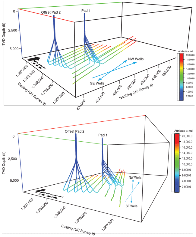
FIGURE 3
Pad 1 Well Trajectories (BURs up to 16 degrees/100 feet)
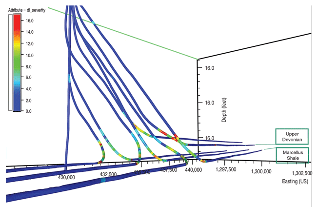
Figure 2 shows two views of Pad 1 and Pad 2 well trajectories. Pad 1 had a combination of southeast- and northwest-oriented horizontal sections, while Pad 2 had only northwest wells. The color code represents measured depth. Figure 3 shows 2-D and 3-D views of Pad 1 well trajectories developed for the 8¾-inch curve section with planned BURs between 8 and 10 degrees/100 feet and horizontal sections in the Upper Devonian (Rhinestreet and Burkett shales) as well as the Middle Devonian (Marcellus). BURs were achieved up to 16 degrees/100 feet. The length of the 8¾-inch section ranged from 4,400 to 14,700 feet. The color code represents dogleg severity (DLS).
Optimizing the horizontal spacing between wells in the lease area makes it possible to develop two formations from the same surface location. The horizontal spacing was roughly 740 feet for all the wells at the same TVD, and the two Upper Devonian wells (1J and 1I) were planned between the six Middle Devonian wells (1A, 1B, 1C, 1D, 1E and 1F) for better reservoir drainage.
The multidisciplinary approach not only defined geological challenges for reservoir navigation, but also allowed the team to deliver action plans designed to implement adjusted reservoir navigation techniques. For example, geosteering was expected to face an updip formation in the Upper Devonian that required dedicated attention, based on previous Burkett Shale experience in adjacent areas.
In the Middle Devonian, bed dip undulations were expected to cause oversteering in offset wells, creating a challenge to keep laterals in zone. The amount of directional drilling required to maintain the BHA in the sweet spot could generate wellbore tortuosity and abnormal torque and drag.
Matched Bit/BHA Design
CONSOL Energy has been using HBRSS technology since 2011 in Pennsylvania, Ohio, and West Virginia. Honing its skills by collectively drilling more than 1 million feet led to establishing best practices. Figure 4 shows the company’s evolution in terms of average footage drilled, illustrating the step change accomplished on PIT wells to expand the technology’s technical limits.
The BHA and drilling progressions led to implementing a motor-assisted BHA design to allow for longer laterals and increased rate of penetration. A reduced motor speed was introduced while drilling Pad 2 wells and became the standard for the area.
FIGURE 4
HBRSS Average Footage Drilled in Marcellus and Utica
(CONSOL Energy = CNX)
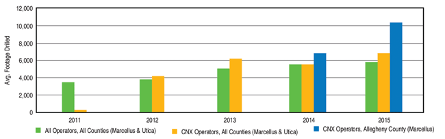
FIGURE 5
Pad 1 Optimized Bit/BHA Design
And Finite Element Analysis Lateral Deflection Results
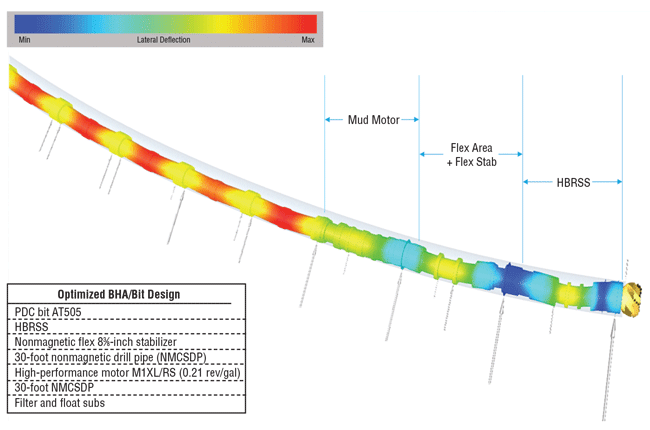
Benefits include additional bit torque at lower bit speed, increased drilling efficiency, and protecting the bit from abnormal damage while drilling hard/soft interbedded formations. The motor is specially designed to run through high-DLS curves while providing additional rotation and handling high differential pressures.
Figure 5 shows the optimized PDC bit/BHA matching design utilized on Pad 1. The entire BHA underwent finite element analysis to check BUR capabilities and bending moment limits, in addition to static and dynamic scrutiny to ensure performance. Besides high dogleg capabilities, HBRSS technology is able to precisely drill vertical, curve, and lateral sections in one run. Automated, closed-loop steering control allows continuous steering for critical wellbore placement in pad drilling with limited spacing.
The system features real-time, near-bit inclination for holding tangents, BUR projections ahead, accurate landing projections, and TVD control during drilling. In addition, real-time near-bit bulk and up/down gamma provide crucial data for reservoir navigation in long-lateral wells, while real-time near-bit vibration sensors enable drilling parameter optimization without compromising wellbore stability or tool reliability.
Pad 1 wells had two main segments to be drilled in one run: vertical/curve and horizontal landing/lateral. In this area, the vertical and curve sections are characterized by highly interbedded abrasive silt and soft shale formations. The silt has infiltrated the shale, making it hard to anticipate or observe with gamma readings while drilling. It is important to maintain proper drilling parameters to prevent damage and premature cutter wear on the bit.
The landing and lateral sections are characterized by clean shale and minimal risk of bit damage. Once the well enters the Burkett, this section is mostly easy drilling the rest of the way through the Marcellus with the exception of the Tully, where controlled drilling may be necessary. Should the BHA fall out of zone, the lower boundary below the Marcellus, represented by the Onondaga Limestone, can cause abnormal bit damage because of its harder lithological characteristics.
The one-run goal meant the HBRSS-customized PDC bit design had to encompass durability, stability, consistent BURs, fine-tuned steering capabilities, endurance, and fast penetration rates while delivering long and reliable laterals. These key features were integrated into a five-bladed PDC bit with 16-millimeter cutters customized for the Marcellus Shale.
Communications Workflow
The workflow implemented on Pad 1 wells included real-time data streaming between the rig and office personnel. Using well-site information transfer standard markup language, data from the rig (weight on bit, torque, flow rate, rpm, standpipe pressure, differential pressure, etc.) and from the HBRSS system itself (surveys, bulk and up/down gamma, vibrations, steering commands, etc.) could be viewed by off-site personnel 30 seconds after they were recorded in the database. This allowed geologists, reservoir navigation specialists, and other personnel to quickly observe trends between parameters, predict apparent formation bed dips before a survey post, and make changes to stay in the assigned drilling window.
In addition, drilling coordinators could closely monitor overall performance and key performance indicators (KPIs) such as the amount of build in the curve section and the effects of drilling parameters on BUR or ROP.
Although the PIT project was a new development area for CONSOL Energy, the company had drilled hundreds of Marcellus wells with HBRSS technology. This helped build a trust level between the operator’s geology team and the service provider’s reservoir navigation team, and gave reservoir navigation experts the freedom to make steering changes without prior approval under certain circumstances. The reservoir navigation team could make inclination changes of less than 0.5 degree/stand, which enabled quicker changes for overall better drilling performance.
The workflow usually consisted of the reservoir navigation team contacting the directional driller with an inclination setting. The change often was made at the start of the stand, so the driller could pair it with any other needed changes to minimize overall downlinks.
Communication between these two parties was not limited to drilling plan adjustments, however. If the directional driller saw an unexpected change in azimuth or inclination, he discussed it with reservoir navigation personnel to formulate a plan to get into a better drilling zone within the target window.
This communication enabled the drilling, reservoir navigation, and geology groups to combine goals into the singular task of drilling the smoothest and fastest well possible while staying in zone 100 percent of the time.
The reservoir navigation group provided constant e-mail updates to all pertinent operator and service company personnel from the start of the curve to TD. Updates were sent at every stand in the curve and every two-three stands in the lateral to show the wellbore’s actual position in relation to formations of interest and the target window. The updates also provided apparent bed dips and comments about any stratigraphic movements or drilling issues that had occurred since the last update.
Crucial Capabilities
There were several best practices agreed on for each on- and off-bottom situation. Most importantly, these best practices were identified by on-site personnel working with the optimization team’s off-site personnel to provide a sense of ownership and add to the team’s motivation and commitment. Establishing the best combination of drilling parameters with steering commands using real-time monitoring drove the successful results on Pad 1 wells.
Because this was a new drilling area for CONSOL Energy, a conservative approach was taken in developing the drilling parameter road map (weight on bit, rpm, flow rate, etc.). Incremental adjustments were made after each dull bit analysis along with overall performance metrics (drilling dynamics, ROP, in-target percentage, etc.). While drilling the curve sections, an increase in bit rpm combined with proper steer force resulted in higher BURs and ROP. Near-bit inclination was used to project ahead and quickly determine BURs.
Among the benefits of HBRSS technology, three capabilities were crucial to horizontal drilling: distinguishing the gamma ray readings above and below the tool, holding a specific target inclination, and obtaining additional tool-specific data for azimuth control.
The Marcellus Shale has distinct gamma ray readings throughout the formation, and the large contrast facilitates easier lateral navigation. Once landed, the HBRSS system was set to automatically steer to a desired target inclination. The command was downlinked through small mud flow variations and decoded by the downhole tool, which then applied the right amount of force to hold angle, minimizing wellbore tortuosity. This automated downhole system is essential in geosteering Marcellus wells, where the sweet spot often is a narrow window influenced by quick bed dip changes.
Another important factor was reducing connection times. The rig crew was motivated to drill the equivalent of one mile in 24 hours. Survey time was optimized using the tool’s capability for flow-off surveys by conducting measurements during connections and allowing the directional driller to get back on bottom quickly. Downlinks were coordinated between the drilling and reservoir navigation groups to save time, and were executed on-the-fly at faster ROPs.
Drilling parameters were managed actively to control both borehole and downhole dynamics. Since torque and drag were the biggest constraints to delivering longer laterals, wellbore quality was assessed and monitored in real time to minimize downhole dysfunctions, improving overall efficiency. Downhole dynamics data monitoring was executed to minimize and manage downhole vibrations that could damage the bit or tool.
Record-Setting Results
Four of the eight Pad 1 wells achieved footage rates up to one mile a day (wells 1E, 1A, 1B and 1I), and five of the eight (wells 1DST1, 1E, 1F, 1J and 1I) remained in the target zone 100 percent of the time. Compared with the Pad 2 wells, Pad 1 wells recorded a 7 percent increase in ROP, a 3 percent increase in total footage drilled, a 2 percent increase in in-zone time, and a 9 percent increase in the amount of footage drilled per day.
FIGURE 6A
Drilling KPIs for Curve and Lateral Sections
(Pad 1 versus Average Offset Pad 2 Wells)
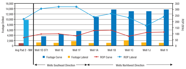
FIGURE 6B
Drilling and Reservoir Navigation KPIs
(Pad 1 versus Average Offset Pad 2 Wells)
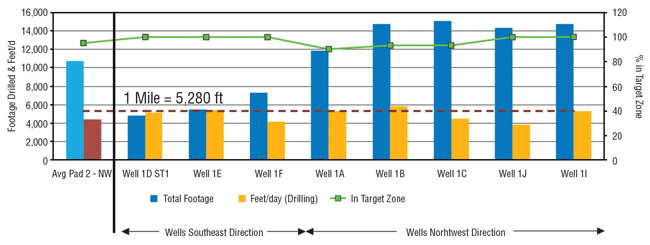
Figures 6A and 6B group Pad 1 wells by chronological order and orientation (southeast versus northwest). Wells 1DST1, 1E and 1F in the southeast direction drilled less footage as a result of lease constraints, but a positive trend of increased footage with 100 percent in-zone time is visible. Figure 6A breaks down some of the KPIs for the curve and lateral sections, while Figure 6B includes drilling KPIs, such as the mile-a-day records side-by-side with the percentage of time in the target zone.
As Pad 1 wells were drilled, best practices were adjusted for each subsequent well. The final well drilled on Pad 1–well 1I–is demonstrative of the outstanding results the project achieved. The well 1I lateral was drilled updip targeting the Upper Devonian Rhinestreet formation, drilling 14,753 total feet in one run. It had a 37 percent longer lateral than the average Pad 2 well, but was drilled with 13 percent higher ROP, recorded drilling rates up to 5,293 feet/day in the lateral, and stayed in-zone 100 percent of the time.
The best drilling rate was recorded on well 1B, which achieved 5,821 feet/day with 93 percent in-zone time while drilling updip in the Marcellus. The longest well drilled in one run was 1C, with 15,084 total feet.
The multidisciplinary team approach combined with HBRSS technology and carefully defined best practices enabled flawless execution of the high-BUR curve and long lateral sections in one-run drilling operations on the Pad 1 wells, and set a new standard for future pads on the PIT airport project as well as other locations across the Marcellus play.
Editor’s Note: The authors acknowledge Baker Hughes’ Scott Bauer and Boris Castro for their contributions to the PIT project and the preceding article.
KEVIN GORR is a drilling engineer at CONSOL Energy, responsible for the company’s West Virginia and Virginia assets while also assisting with the Pittsburgh airport project. He joined CONSOL in 2012 as a field engineer in the Marcellus, Upper Devonian, and Utica Shale plays. Gorr holds a B.S. in civil and environmental engineering from Carnegie Mellon University, and an M.B.A. in corporate strategy and finance from the University of Michigan.
RYAN COFFMAN is a drilling engineer II at CONSOL Energy, responsible for managing Pennsylvania assets, and the PIT drilling operations. He joined CONSOL in 2010 as a drilling engineer, and subsequently served as assistant rig supervisor and rig supervisor. Coffman holds a B.S. in environmental systems engineering from Pennsylvania State University.
LUKE BEEBE is drilling manager at CONSOL Energy. He joined the company in 2008, and served as the drilling manager for the Southwest Pennsylvania region until 2013, when he was promoted to drilling engineer adviser. He holds a B.S. in petroleum engineering from Marietta College.
DENISE AZUAGA LIVINGSTON is automated drilling services technical adviser for North America at Baker Hughes. She has 15 years of experience in onshore and offshore drilling in North America, Europe, Latin America and Africa. She holds a B.S. in chemical engineering from Rio de Janeiro Federal University, a post-graduate degree in petroleum engineering from Pontifical Catholic University, and an M.S. in energy and environmental planning from COPPE/UFRJ.
DREW ANDES is a drilling team lead at Baker Hughes. He joined the company in 2009 and has held various roles within the drilling services operations group. He has experience with measurement while drilling and directional drilling, and was involved with the first AutoTrak™ Curve RSS run in the Northeast for Baker Hughes. He holds a B.S. in electrical engineering and a B.S. in biometric systems from West Virginia University.
MCKENNA CZERNESKI is a drilling applications engineer at Baker Hughes. She joined the company in 2010 as an MWD/LWD field engineer, and then served as an MWD/LWD field operations coordinator. Czerneski holds a B.S. in petroleum engineering from Montana Tech of the University of Montana.
For other great articles about exploration, drilling, completions and production, subscribe to The American Oil & Gas Reporter and bookmark www.aogr.com.