


Production and Processing
Production Characteristics Of Liquids-Rich Resource Plays Challenge Facility Design
By Michael W. Conder and Kevin A. Lawlor
DENVER–With domestic drilling activity focused on liquids-rich unconventional plays, most wells being drilled today produce both liquids and natural gas. In fact, according to the U.S. Information Administration, 77 percent of the “oil” wells and 79 percent of the “gas” wells drilled in 2012 produced some combination of liquids and gas.
Billions of dollars are spent each year to design and build well pads, pipelines and facilities to compress and dehydrate natural gas as well as stabilize crude oil and condensate. Tight oil and liquids-rich plays such as the Bakken, Eagle Ford, Utica, Marcellus and Niobrara present unique challenges to production, gathering and processing infrastructure. This is particularly true in areas lacking gas infrastructure, or where existing infrastructure is undersized. Downstream markets for oil, natural gas and natural gas liquids products often are constrained by facility/take-away limitations, and projects to relieve those constraints have high capital costs and long cycle times.
However, with the right infrastructure strategies and concepts, operators can mitigate the challenges from the wellhead to the sales point in designing production, compression, crude/oil condensate stabilization, pipeline, and treating and processing facilities for tight plays with oil, dry gas and/or NGL production streams.
The extreme production decline rates of individual wells in these plays require special attention to piping and equipment design. Critical infrastructure design variable such as gas-to-oil ratios, the composition of the crude oil and natural gas, and operating pressures and temperatures can differ dramatically between plays, and even between wells in relatively close proximity within the same play. Consequently, a successful concept in one part of a play might not be the best option in another play, or another part of the same play. The move to pad drilling only adds to the challenges involved with facility design.
Production Characteristics
The characteristics of the production stream in unconventional resource plays vary widely, but it is important to understand the differences in these characteristics and how they affect infrastructure to properly design facilities. Table 1 illustrates some of the significant differences among five unconventional plays.
TABLE 1
Typical Characteristics of Unconventional Plays
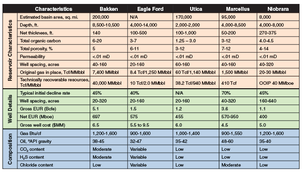
Similar challenges are encountered in designing infrastructure components such as production facilities, central compression, oil and separation, dehydration, crude oil/condensate stabilization, and NGL extraction facilities. The major factors that greatly impact the economical design of production equipment and midstream infrastructure include:
- Unusual production characteristics (i.e., high initial production followed by steep decline curves);
- Variable compositions of gas, NGL and oil products;
- Increased use of pad drilling techniques, which requires larger capacities for central compression, dehydration and natural gas liquid extraction facilities;
- Ever-changing environmental and safety regulations, as well as fluctuating commodity prices.
One of the most challenging production characteristics for facility design is the combination of high IPs and high production decline rates. A conventional gas well typically declines at less than 20 percent annually. In contrast, unconventional wells frequently have hyperbolic decline rates as high as 25 percent per month until the wells reach a pseudo steady-state decline rate. This process can take 12 to 36 months, depending on the formation, lateral length, well spacing and completion techniques. The challenge these conditions present is primarily economic, and involves designing facilities in the most economical manner to handle the wide range of production rates.
Steep production declines require careful design of gathering, processing and pipeline systems to provide an economical balance between the initial production capacity desired by a producer and the long-term cash flows expected to be derived from the production.
Some of the problems caused by steep decline rates can be reduced or minimized by using large central facilities. However, given the nature of low-permeability formations, care must be taken in forecasting a field’s long-term production profile since interference effects in wells generally take years to materialize. Failing to account properly for these effects could result in designing midstream systems with far too much capacity that will never be utilized economically.
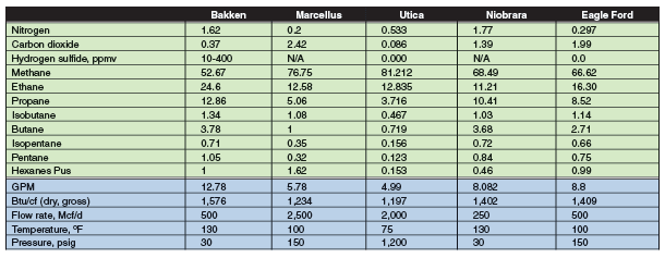
A fundamental principle of physics and geology is that bottom-hole pressure and temperature increase as true vertical depth increases. Variations in temperature and pressure with formation depth create variations in hydrocarbon compositions. The deeper the well, the more likely it is to have less complex hydrocarbons. Therefore, as depth increases, the GOR ratio generally increases for oil wells and the Btu per cubic foot (Btu/cf) generally decreases for gas wells. This can be seen clearly in both the Marcellus and Eagle Ford plays, where hydrocarbon compositions range from heating values of 900 to 1,600 Btu/cf.
Hydrocarbon content variations can cause numerous problems. Chief among them is accurately predicting hydrocarbon vapor formation. Fluids from wells in these plays are at their bubble point, and as pressures decrease to meet production equipment requirements or heat is applied through stabilization or compression, gas vapors can break out from the production stream. Accurately predicting the amount and composition of vapors is critical to facility design. Table 2 shows typical compositions and initial production rates for the five plays in Table 1.
TABLE 2
Typical Unconventional Analyses and
Initial Delivery Conditions
Compounding an already challenging facility design and engineering situation, environmental regulations are becoming ever-more stringent for production and processing infrastructure. This is particularly the case regarding the amount of hydrocarbons a facility can vent to the atmosphere, and allowable emissions from compressor and pump engines.
Oil Handling Facilities
Wellhead oil facilities historically have been fairly simple installations. Until the advent of directional drilling, facilities were limited to supporting a single vertical well with a production separator or heater treater, a couple of oil tanks, a water tank or vault, and possibly a beam pump. With directional drilling, facilities have expanded to support multiple wells by adding additional production separators or heater treaters, and more oil and water tanks.
In horizontal tight oil plays, common production facilities can handle 16 or more wells per pad with high IP oil, gas and water flows. Equipment and systems have been evolving to meet the new demands. For instance, operators have responded to venting concerns by installing larger tank batteries with vapor collection systems, open flares, enclosed emission combustion devices (ECDs), and vapor recovery units (VRUs). Oil and gas handling at these facilities is much more integrated that in the past, but is also more expensive and requires more engineering and design.
Producing companies’ basic oil handling concepts continue to evolve in response to the production requirements for high-decline horizontal oil wells. Gone are the days of field design and the installation of a few pieces of equipment; tight oil play facilities are major installations that cost millions of dollars. Many companies are treating them in the same manner as traditional gas processing plants, with full engineering drawings, process safety management-style safety reviews, and dedicated operational staff.
For production separation, the trend is to use common bulk separators sized to handle production from four to eight wells, with a parallel single-well test separator to provide allocation and individual well production monitoring. This cuts overall installation costs by reducing the total number of separators on the pad and requiring a smaller pad footprint.
Two-stage fired horizontal separators also are being used for primary well stream water, gas and oil separation. Some operators are accomplishing this with two single-stage separators in series (one high pressure and one low pressure). Others are using high/low-pressure (HLP) separators, which have a vertical two-stage scrubber to separate the bulk of the produced gas from the water and oil, and an integral fired horizontal three-phase separator that operates at lower pressure. This design keeps the bulk of the produced gas at full line pressure, minimizing the load on the VRU compression to the flash gas generated from further depressuring the oil. In operation, the high stage runs at gathering system pressure and the lower stage runs 20-50 psig.
Vapor Recovery
Vapor recovery requirements have added a new dimension in the final oil handling. Classic vapor recovery systems have been installed with the VRU compressor taking suction off the top of the oil tanks and compressing it to full gathering line pressure. Traditional VRU design has four potential problems:
- Tight pressure control needed, since standard tanks can handle only 8-16 ounces per square inch (oz/in2) pressure and 0.5 oz/in2 vacuum;
- Probable oxygen ingress from leaking tank gauge hatches and/or operators opening the hatches for manual gauging;
- Problems handling gas surges; and
- Excessive liquids condensing of the VRU discharge gas, resulting in large liquid recycle streams.
The latter problem is being handled by creative VRU design schemes, while the other problems are minimized by the use of vapor recovery towers (VRTs), which are rapidly becoming the standard in tight oil plays.
A VRT is simply a tall, empty vessel that provides a surge volume and flash gas capture point for the final oil flash. It is located between the production separators and the oil tank battery, and is about 10 feet taller than the highest oil tank. It is designed to provide a positive suction point for the VRU compression, and can be a single vessel per well or a larger vessel for multiple of wells.
Flashing oil is fed to the top of the VRT, where the bulk of the flash gas separates from the oil. The oil outlet line has a “dip tube” from a point just below the oil inlet to a point close to the bottom of the vessel. This requires the incoming oil to travel to the bottom of the vessel before it flows up the dip tube and out the upper side of the vessel. The oil then gravity flows to the tanks. This design provides a positive seal against air entrainment into the VRU gas stream.
The VRT normally operates at about 1 psig when the oil level is near the top of the vessel. When a gas surge is greater than the capacity of the VRU compression, VRT pressure increases and pushes the oil toward the bottom of the vessel. This keeps the oil flowing while increasing the VRU capacity (as a result of the increased pressure) to better handle the gas surge. In effect, the VRT acts as a gas surge vessel, analogous to a surge drum for a liquid pump.
Oil and water tank batteries have evolved also to meet the needs of oil shale plays. Batteries historically have been built with a few 300-400 barrel tanks, but they have been supplanted with larger batteries of 500-, 750- and even 1,000-bbl tanks fitted with level transmitters to minimize tank gauging (which helps reduce volatile organic compound emissions and air ingression associated with manual gauging). The level information is often transmitted by supervisory control and data acquisition systems, allowing operators to schedule tank load-outs more efficiently.
Enclosed combustion devices are a major addition to tank batteries. ECDs are basically enclosed flares, burning the small amounts of flash gas that remains after the VRT towers. These units also provide combustion for larger volumes if the VRUs are not able to meet the gas demands of the system. ECDs were built originally by local shops with minimal engineering, but more highly engineered devices are coming onto the market. They typically can handle 100 Mcf/day vent gas with a heating value of 2,000-3,000 Btu/cf. It is common to see tank batteries with a battery of six to eight ECDs installed on the vent lines.
Oil Stabilization
Oil pipelines and rail car shipping services have basic sediment and water (BS&W) requirements that are more restrictive than truck hauling. Typical pipeline specifications are 0.2-0.3 percent BS&W. Standard separators are frequently unable to meet these lower levels under all operating conditions.
Producers are addressing this issue by installing centralized oil polishing facilities that receive and heat the incoming oil, then hold it in vertical tanks for 12-24 hours. Total installed costs for these plants are $350-$500 per bbl/d capacity. At a savings of only $1/bbl, polishing plants can pay out in 12-24 months.
Oil field operations, especially during hydraulic fracturing, frequently can produce oil/water emulsions that cannot be broken in field units. These emulsions are sold at a deep discount or sent to disposal wells. Oil polishing facilities can be designed to accept these emulsions and break them by heating, chemical injection and settling time. This can provide a significant income stream, especially if a producer handles emulsions from other producers as well as from his own operations.
Pipeline pricing is normally based on West Texas Intermediate oil with 41-42 degrees API gravity. Many oil shale plays produce oil with much higher gravity, often 50-55 degrees. Pricing at major terminals such as Cushing, Ok., deducts $0.50-$3.00 per barrel for higher-gravity oil. This has led to installing pad or centralized oil stabilization units that provide lower gravity oil than with flash stabilization. The stabilizer reduces the oil volume slightly since some of the lighter ends are removed, but it can significantly increase the oil value.
For example, the installed cost of a 2,500 bbl/d pad-style centralized stabilization unit is about $400,000. This design can increase oil sales by $750-$4,500 a day with payout in six to 24 months, even with the volume reduction from removing light ends. Moreover, the gas from the stabilizer units is fairly rich with good value at gas processing plants, often netting a 50-75 percent price premium because of the liquids upgrade value (since it is such a rich gas, however, it requires careful handling in the associated VRU compression).
Gas Handling Facilities
The significant volumes of rich gas typically produced in oil resource plays can present a win/win situation for the operator if VRU compression is installed to capture flash vapors from oil depressuring. The grouping of wells on a pad provides enough critical mass to make vapor recovery technically and economically feasible.
TABLE 3
Typical Per-Well Gas Balance: Horizontal Oil Well
with Gas Lift
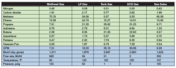
Table 3 shows gas production for a gas-lifted horizontal oil well producing 450 bbl/d. In this case, vapor recovery increases gas production by ±13 percent, net Btu production by ±25 percent and potential liquids recovery by ±45 percent, while also reducing VOC emissions from a combustor or flare by an amount exceeding an order of magnitude.
VRUs have been employed in gas systems for decades. The basic concepts of VRU compressors have not changed, but some important details and design concepts have been developed to handle the heavy gas from liquids-rich plays–especially in colder weather climates such as North Dakota, Ohio and Pennsylvania–which requires facility designers to pay special attention to compressor types, gas temperatures, gas pressures, liquid dropout and liquid recycle volumes.
The HLP production separator and VRT design concept lends itself to VRU design. Typically, VRT gas is compressed in a low-pressure VRU (LP VRU) from 1 psig to 30-50 psig. The LP VRU then mixes with gas from oil flash equipment at the same pressures before flowing to a high-pressure VRU (HP VRU). This design can reduce VRU horsepower by 25-35 percent. Discharge temperatures of the LP VRU are carefully controlled to prevent liquid condensation and recycling. The gas tends to be so heavy that recycling could lead to doubling or tripling the volume through the compressor.
The pressure control system on the LP VRU is also critical. It needs to be responsive enough to prevent overcompression (vacuum operation) as well as handling gas surges, which are normal with these wells. These compressors tend to be screw or rotary vane units. Reciprocating compressors are used less frequently, in part because of the potential for pulling a vacuum in the cylinders caused by valve losses (any leaks would allow oxygen into the system).
The HP VRU can be a more flexible system, since it can operate at a range of suction and discharge pressures. These compressors tend to be screw compressors up to a gathering system discharge pressure of 300-350 psig. Higher pressures usually require using multistage reciprocating compressors.
Discharge temperatures on these units also must be carefully controlled, since they are at similar risk for excessive liquid condensation/gas recycling. Some installations bypass the final cooler entirely and blend the relatively small volume of hot gas into the total produced gas while not increasing the total gas temperature beyond acceptable limits.
Gas Lift, Metering Solutions
Many tight oil and liquids-rich gas plays have reservoirs with limited pressures, requiring some sort of artificial lift. While surface-mounted beam pumps and plunger lift systems are being used, many wells are using gas lift systems that typically take the gas produced from the well, compress it to 600-1,200 psig, and then reinject it back into the well. The extra gas flow increases the velocity of the fluid in the wellbore, allowing it be cleared of fluids.
Compression for gas lift systems started as local compression on the well pads, feeding a limited number of wells. The compressors typically were leased, and sized from 50-200 horsepower to flow 300 and 1,200 Mcf/d of lift gas. Recent trends are toward more centralized compression, with units sized up to 1,500 HP and larger, providing lift gas to 10-20 wells per compressor.
Gas lift systems require a gas source that is independent of the well undergoing gas lift to “kick start” gas production, if gas lift is interrupted and the well loads up enough to cut gas production. The source could be a company-owned gathering system, buy back from a third-party gathering system, or adjacent wells.
Oil metering was not very important in single, vertical well facilities, since it was often done by tank gauging. However, facilities handling multiple horizontal wells producing large liquid volumes normally need to make full use of tank storage volumes, since installing dedicated tanks with segregated storage may not be economically feasible. These facilities can benefit from comingling the liquid production.
Liquid measurement is still normally required for well performance monitoring and production reporting/allocation. Instead of measuring oil production from the separators using orifice meters, producers are using coriolis mass meters to eliminate metering errors caused by density and temperature changes. In addition, some producers are using modified cement turbine meters (initially developed to measure cement slurries) instead of orifice meters to measure water production.
Orifice meters remain the dominant gas metering device, although ultrasonic metering is gaining favor where gas flows are large enough to justify the higher cost. Metering around VRUs requires careful attention to installation and location. Meter lead lines need to be free-draining, and may need to be insulated and/or heat traced in cold weather climates. In addition, meters must be located in the process flow in locations where they do not measure recycle volumes or where two-phase flow may occur.
Facility Design Concepts
FIGURE 1
Hypothetical Production Facility Flow Sheet
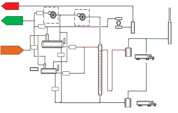
All of these components are part of the basic pad design that has evolved for oil shale plays. The flow diagram in Figure 1 illustrates a complete pad design for a hypothetical facility based on:
- 16 wells with IP rates averaging 500 bbl/d, a 25 percent water cut, and a GOR of 1,000;
- Three days of oil and water storage;
- Full vapor recovery;
- Pad-installed gas lift compression; and
- Truck hauling.
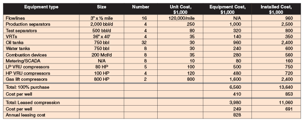
Table 4 shows the equipment details and costs for this facility.
TABLE 4
Hypothetical Centralized Oil Facility Cost (Full Build-Out)
One of the biggest facility design challenges is making efficient use and reuse of the equipment involved. With wells declining by 60-75 percent in their first year of operation, any equipment large enough to handle IP flows will be greatly oversized in a matter of months. Operators have been addressing this problem through well scheduling as well as relocating equipment for one site to another for multiple installations.
In regard to the first strategy, operators are adjusting drilling schedules to drill groups of perhaps four to eight wells every six months or so. This allows central facilities to be sized for volumes less than the total IP rates of 16-32 wells. This “staged” approach allows new wells to start production when the wells drilled in the previous stage decline to 50 percent of their IP rates. In this way, production from each pad is leveled and the facilities can operate at a comfortable load for a fairly long time to provide operational and cost efficiencies.
The other approach is to relocate equipment from a pad once production has declined to 50 percent of the IP rate to new pads with high IPs. Most central facilities are built with multiple units of each equipment type–eight to 16 production separators, four to 16 VRTs, six to eight VRUs, 16 to 24 oil and water tanks, four to eight ECDs, etc. With the possible exception of production separators, these units can be moved and reinstalled on new pads as needed.
While the staged drilling scheduling concept provides significantly better savings than relocating equipment (which has equipment removal/installation costs), the lowest overall cost solution may be achieved combining both of these concepts, whether the operator owns or leases the compression and other major equipment components.
Gathering Configurations
Four basic gathering system design concepts emerged for dry gas shales plays: linear, nodal, circular, or a combination. However, since the associated gas from the oil shale plays contains much more heavy components, there is a greater need to design for liquid dropout in gathering lines. Daily pipeline liquid production can be 40 bbl/MMcf and higher, even in low-pressure systems, making it essential to design gathering systems to handle high liquid volumes.
All gathering laterals should be fitted with pig launchers and receivers, and a formal pigging procedure and schedule must be followed. The linear-style gathering system lends itself well to a system needing frequent pigging. It provides long pigging runs and is easier to pig than a circular system, and can require less manpower than a multilateral nodal style system.
Gathering line sizing is more critical in oil shale plays than in dry gas plays, where oversizing gathering lines for future expansion has little downside other than the capital risk. Larger lines provide lower pressure drops and that can help increase compression efficiency. On the other hand, oversizing lines in oil plays actually can increase operating problems. Oversized lines have more liquid holdup capacity since line velocities are lower, reducing line gas sweeping. This will either increase slug volumes that need to be handled or require much more frequent pigging to keep slug volumes at manageable levels.
Gathering lines in some tight oil plays may be limited to steel pipe, even in cases where pressures normally would allow less expensive polytheylene or composite pipe. Production separators can have failures that send large oil volumes into the gathering lines, which can congeal in the pipelines if the oil has relatively low gravity or high paraffin content.
Such situations normally are cleared by hot oiling the lines at temperatures that are unsuitable for polytheylene or composite pipe. Pipe laterals in these systems should be designed with a sufficient number and size of valves to facilitate hot oiling.
The delivery point of these gathering systems is normally a pipeline, compressor booster station or processing plant. New plants are designed for handling high pipeline liquid volumes and incorporate slug catchers and condensate stabilizers. Older plants converted to handle production from horizontal drilling may need to have these systems upgraded or replaced with larger systems. Liquids handling often does not require changes in plant operation; only changes to handle the volumes.
Older compressor booster stations often were built with minimal attention to liquids handling. They were designed to dump liquids directly into atmospheric tanks from pig receivers, two-phase inlet scrubbers, high-pressure discharge scrubbers, and other gas/liquid separating devices. This design results in significant VOC emissions from the flashing of the liquids.
FIGURE 2
Compression Booster Station Process Flow
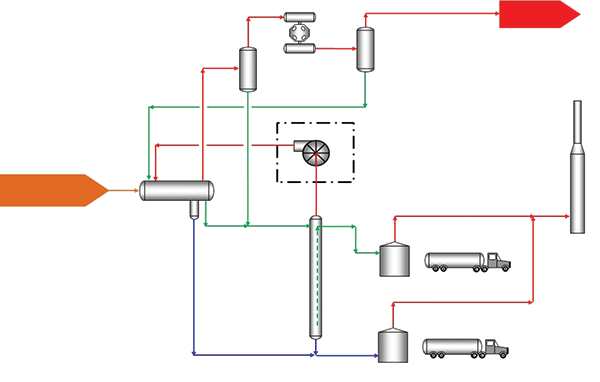
Changes in emission requirements, such as the new U.S. Environmental Protection Agency’s “Quad O” regulations, require these emissions to be captured. Figure 2 illustrates the process flow of a compression booster station designed to meet these requirements.
Key provisions of the design include:
- Liquids at inlet pressure go to a VRT;
- Vapors from the VRT are recycled to the station inlet;
- Higher-pressure dump liquids also are diverted to the station inlet;
- Tank vapors are collected and sent to an ECD for combustion.
Liquids Recovery
The choice of which process to use to separate hydrocarbon liquids depends on the quantity of natural gas to be processed, the composition of the natural gas, the local infrastructure for NGL sales and distribution, commodity pricing, and economics. The common NGL extraction processes are Joule-Thompson (JT) plants, medium-temperature refrigeration plants, low-temperature refrigeration plants and turbo expander-based cryogenic plants. Careful consideration should be made when choosing a gas processing design since the facility investments are very large and the revenue impacts between different technologies can be considerable.
If the primary requirement for processing the natural gas stream is to meet a hydrocarbon dew point, Btu/cf or Wobbe number specification, the best choices are likely to be a JT expansion plant or a medium-temperature refrigeration plant. Both processes can achieve hydrocarbon dew points of 10 to 40 degrees Fahrenheit.
JT plants utilize the cooling achieved through a pressure drop across a control valve to extract NGLs. They are common on wells flowing less than 10 MMcf/d with relatively low-BTU gas. The primary advantages are that they are inexpensive to purchase and install, and simple to operate. The disadvantages are low liquid extraction efficiencies and high operating cost if compression is needed to increase inlet or outlet gas pressures. Depending on Btu content, it may be impossible to achieve sales gas Btu specifications with a JT plant.
Medium-temperature refrigeration units typically are used if production rates are higher than 10 MMcf/d or if the gas is rich in hydrocarbons. The units are designed to chill the gas with very little pressure drop using a water/freon or water/propane refrigeration scheme. Often, they are equipped with electrical motor-driven refrigeration compression to save weight and simplify operations.
If maximizing the economics of NGL extraction is the primary driver for installing a processing facility, the best option would be a low-temperature refrigeration unit or a turbo-expander plant. The choice between the two technologies depends on the composition of the gas and the local infrastructure.
Most low-temperature refrigeration units use propane as the refrigeration medium. They are less available than medium-temperature units and may need to be custom designed and built. These units typically can provide hydrocarbon dew points to -40 degrees F. Advantages are ease of operations and low fuel consumption resulting from the minor pressure drop required by the process. A significant disadvantage is that these units cannot recover ethane and propane as efficiently as a turbo-expander.
Turbo-expander plants provide the greatest economic rates of return and operational flexibility. They use an isentropic expansion of the gas to reduce the temperature to between -130 and -160 degrees to recover the majority of ethane within a gas stream. However, expansion means additional compression usually is required to meet sales gas transmission line pressures.
Turbo-expanders can be sized from 20 MMcf/d to 1,000 MMcf/d, and there are many choices of process configurations. Standard designs for gas processing plants that utilize the gas subcooled process are readily available. Advantages include availability and cost efficiency in ethane recovery. The main disadvantage is the ability to reject ethane cost effectively compared with other cryogenic process configurations.
Liquids-rich shale plays represent the future of the industry for many years to come, but success requires overcoming the complexities these plays represent to economic, safety and environmental aspects of facility design. Going forward, a company’s ability to economically design and build production, gathering, compression and processing facilities, and to operate them efficiently and safely to optimize revenues and comply with all regulatory requirements will remain one of the industry’s biggest challenges.
MICHAEL W. CONDER is a senior staff technical adviser for Denver-headquartered Bonanza Creek Energy Inc. He has more than 30 years in engineering design and operations, and has worked for design engineering firms such as Ortloff Mountain States Corporation, The Pro-Quip Corporation, Propak System Ltd., Bateman Engineering and Pearl Process Systems, as well as for operating companies including Maple Gas, Vessels Energy, Duke Energy Field Services, Samson Resources Company and Berry Petroleum. Conder also has managed a gas gathering and processing facility, and is co-inventor for a patent related to carbon capture technology. He serves on the Laurance Reid Gas Conditioning Conference’s Advisory Committee. Conder holds a B.S. in mechanical engineering from the University of Arizona.
KEVIN A. LAWLOR is vice president of engineering at Houston-based Axip Energy Services. Lawlor has 18 years of oil and gas industry experience working for such companies as NATCO, Fluor Daniel, ONEOK and Samson Resources Company in designing, operating and maintaining surface facilities. He served as manager of midstream operations and engineering for Samson Resources before joining Axip in 2012. Lawlor is the past chairman of the Facility Design Committee for the Gas Processors Association He holds a B.S. and an M.S. in chemical engineering from the University of Tulsa.
For other great articles about exploration, drilling, completions and production, subscribe to The American Oil & Gas Reporter and bookmark www.aogr.com.