


Technologies Optimize Flow Assurance
By Phaneendra Kondapi, Jefferson Creek, Y. Doreen Chin and Randi Moe
HOUSTON–With offshore development migrating into ever-deeper waters, the industry is relying on subsea technology to facilitate increased oil and gas recovery while lowering costs and improving safety and operating efficiencies. The deepwater reservoirs being developed today also are becoming more challenging, with greater subsurface depths, higher pressures and temperatures, and more complex fluid systems.
Given these trends, the need has never been greater to understand flow assurance risks and design effective strategies to mitigate those risks. Flow assurance can be expressed as the coupling of multiphase flow and fluid phase behavior. It requires understanding both steady-state and transient multiphase flows, as well as fluid properties, fluid compositions, pressure volume temperature (PVT) characteristics, and other fluid phase behaviors from the reservoir to the topsides process equipment throughout the life of field to prevent upset conditions.
Flow assurance strategies are on the critical path to reducing overall development costs and ensuring safe and reliable subsea production operations. Since it has such a significant impact on field development and production system design, it is important to establish at an early phase of project planning whether flow assurance is needed. From the earliest stages onward, flow assurance operating philosophy should permeate each phase of field development engineering and project execution revealed as flow assurance design requirements. System modeling helps identify design limits and potential production issues.
FIGURE 1
Flow Assurance in Project Development and Execution Process
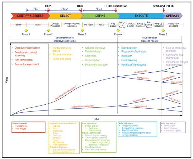
The best opportunity to make a positive impact on the life cycle of a major subsea capital project is during the early conceptual and planning stages before a financial investment decision has been made. Front-end loading (FEL) is the process for the conceptual development of a project and refers to the preproject planning stage, feasibility analysis to verify the project is technically and commercially viable, conceptual planning, front-end engineering design (FEED) to determine the basic specifications for the production facility and early project execution planning.
FIGURE 2
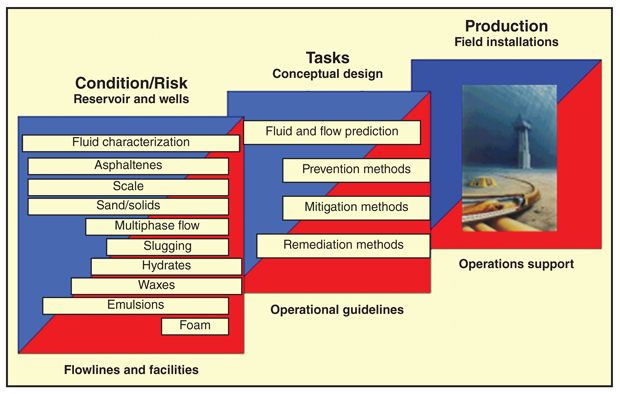
Overview of Flow Assurance Issues
The early stage in a development project’s life cycle is the time when the ability to influence changes in design is relatively high and the cost to make those changes is relatively low. Figure 1 illustrates how flow assurance impacts concept selection, project execution and asset value. Develop sufficient strategic information and engineering analyses to address risks and guide decision making for concept screening exercises. Then the FEED can maximize the potential for success. Sufficient FEL is the key to any successful project, and early engagement of flow assurance is critical for field development and production system concept selection.
FIGURE 3
Flow Assurance Technology Matrix
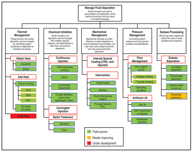
Figure 2 identifies many of the flow assurance issues that can plague field operations and project execution. Despite the large number of potential flow assurance risks, there are only three questions to be answered for a pantheon of problems that can impede flow over the life of a development project:
- Are there flow assurance risks in any operational scenarios?
- How often will the risks require treatment? If the risk is hydrates, for example, answering this question will require investigating how often flowline conditions would allow hydrates to form and require remediation based on flow simulations for steady-state conditions as well as startup/shutdown conditions.
- Can the potential problem be managed effectively by thermal, mechanical and/or chemical means? Again using hydrates as an example, the solution could be thermal (insulation or heat tracing), mechanical (pigging), chemical (inhibitor) or a combination.
Figure 3 summarizes the state of technology to manage flow assurance risks, including preventing problems related to the deposition of hydrates, paraffin, scales and other solids.
Hydrate Inhibition
Hydrate formation is typically the most common concern for subsea flow assurance engineers. If gas or solution gas is present with water, hydrates can form at some point in the life of a field. Traditionally, chemical injection of methanol for oil systems and monoethylene glycol (MEG) for gas systems had been the primary method of hydrate inhibition, although the cost on long subsea flowlines can be high since they contain larger volumes of fluids.
Alternative chemicals are now available such as ethanol for thermodynamic inhibition and low-dosage hydrate inhibitors (LDHI) such as anti-agglomerates and kinetic hydrate inhibitors (KHIs).
LDHIs have unique challenges as well as operating and capital expenditure considerations. Their performance is proven both as stand-alone chemical treatments and as a means of reducing methanol/MEG usage. LDHIs have provided significant benefits compared with thermodynamic inhibitors, and significantly lower inhibitor concentrations and losses caused by evaporation. They reduce capital expenditures through decreased chemical storage and injection requirements, and reduce operating expenses by decreasing chemical consumption and delivery frequency, thereby lowering transportation and manpower costs for chemical handling.
LDHI systems have low toxicities and have been shown to reduce the maintenance requirements on chemical pump and delivery systems, which decrease Health, Safety and Environmental risk. They also can increase production rates in cases where inhibitor injection capacity or flowline capacity is limited. All of these benefits are especially important offshore, where payloads and deck space are at a premium.
Gulf of Mexico applications of LDHI include both oil and gas systems. For example, continuous KHI injection treatment replaced the continuous pumping of methanol for a high-pressure gas condensate well that had been causing hydrates to form in the flowline and manifold. A KHI product from Clariant Oil Services has successfully controlled hydrate formation in the system and replacing methanol with KHI has allowed the operator to reduce the chemical injection rate by 45 gallons a day.
In another application, an antiagglomerant was injected into the uninsulated flowlines of two gas condensate wells that had been shut in by hydrate plugging. Methanol had been pumped into the flowlines, but limited injection rates could not sufficiently treat the produced fluid. Champion Technologies developed an anti-agglomerate chemical package to prevent hydrate blockages for this fluid. The successful performance of this package was verified in a subsea field trial. This inhibitor enabled production rates for both wells to be increased to full production system capacity.
In a black oil example, a well was started up with a high initial methanol injection rate of 1,000 gallons a day because of the methanol pump’s turndown limitations. Needing a more economical hydrate mitigation strategy, the producer elected to use an anti-agglomerate LDHI from Multi-Chem, a Halliburton Service. The chemical was injected continuously into the flowline system without any hydrate issues and methanol injection was completely shut off.
Paraffin Strategies
A combination of chemical (paraffin inhibitors), thermal (insulation), and mechanical (pigging) technologies are being used to manage paraffin problems in subsea flowlines and equipment. For example, in a three-well field development offshore Norway, a production pipeline required pigging every two weeks because of suspected wax deposition in the line. A wax inhibitor from Clariant was applied to effectively treat the produced oil and eliminate paraffin blockages while satisfying the environmental requirements set forth by the Norwegian Pollution Control Authority.
In the Gulf of Mexico, a Multi-Chem paraffin inhibitor successfully treated two gas condensate wells. Production from each well had a paraffin content of about 4%. The paraffin inhibitor inhibited 95% of the wax and reduced the pour point to 30 degrees Fahrenheit.
An effective pigging strategy requires establishing a feasible pig control scheme using differential pressure between the pig launcher and pig receiver as the control mechanism. Production line pressure must be sufficient to drive the pig around the loop, and the system temperature profile has to be within acceptable limits during the entire pigging operation. Methanol or MEG can be injected during startup/shutdown to prevent hydrate formation, but production lines may need to be pigged prior to startup to remove water. Strategies also need to be developed to determine whether a total production shut-in is required for pigging based on the flowline settle-out pressure and temperature.
In-line traps are the most common method of getting pigs in and out of flowlines. The selection of pig traps and the method of launching/receiving pigs depend on several factors. Additional protection for associated launch/receive pipework and valves is required, and the type and size of the pig will have a bearing on the launcher/receiver design. The number of pigs required to be launched/received in the pig train also has an effect on the physical size of the trap and associated pipework required. The pressure rating of the pig trap required to meet system design codes/standards and function also can influence the trap size and design.
The slug catcher and separator should be able to handle the liquid volumes and surges caused by pigging, when most of liquids contained in production lines are swept out. Liquid holdup in the system prior to pigging cannot exceed the maximum physical liquid capacity of the slug catcher and separator or the accumulated liquid in the slug catcher/separator will need to be drained at an equilibrium rate. The pigging operation may have to be stopped to get the pig home if the system's total liquid holdup exceeds twice the capacity of the slug catcher.
Stopping a pig and draining the slug catcher may prove difficult and time consuming and lead to stuck pigs. Usually, the liquid arrives at the slug catcher as one large slug and the liquid is dumped within a relatively short time. Accordingly, the liquid level needs to be monitored and controlled to make sure it does not exceed the slug catcher’s maximum capacity.
Mitigating Common Problems
Chemical solutions also are being successfully applied to mitigate common production problems caused by asphaltene precipitation, scale formation, foaming, emulsions and hydrogen sulfide. There are numerous examples of such applications, including:
- In the Gulf of Mexico, a subsea well with 17% asphaltene content in the produced oil was successfully inhibited with a Multi-Chem asphaltene inhibitor product. The well has remained on line and producing without any blockages, and pigging operations have demonstrated that asphaltenes are kept in solution.
- In another Gulf of Mexico field, two wells with incompatible crude oil were commingled to support production operations, but the commingling resulted in the high-pressure separator filling with asphaltene solids. An asphaltene inhibitor from Baker Hughes, a General Electric company, was injected into the commingled production stream to successfully prevent asphaltene precipitation in the separator.
- Offshore the United Arab Emirates, asphaltene inhibitor and dissolver products from Clariant were squeezed into the formation after production began declining as a result of asphaltene deposits in the tubing and wellbore. Squeeze treatment was selected because no facilities for continuous injection of asphaltene inhibitor were available and coiled tubing installation was economically unattractive. The well production rates increased with time after performing the asphaltene inhibitor squeeze.
- Shell’s BC-10 project in the Campos Basin offshore Brazil is the first project to inject defoaming chemical subsea. The defoamer is injected into a vertical caisson on the seafloor that contains separation and an electric submersible pump.
- In the Gulf of Mexico, an offshore gas well had to be shut in when its production began exceeding the pipeline specification for H2S content. After starting continuous injection of a scavenger product from Multi-Chem into the gas stream at the separator outlet, H2S concentration was reduced from 8 parts per million to less than 2 ppm to allow the well to produce into the pipeline again.
- An H2S scavenger from Clariant was used to treat an offshore gas export pipeline in the North Sea. The scavenger was injected into the wet gas production streams exiting the first- and third-stage separators. The H2S concentration was subsequently reduced from 160 to 20 ppm.
- Also in the North Sea, a producer was able to treat a water-in-oil emulsion for the export oil to meet the pipeline’s 0.3% water content limit using a Clariant demulsifier solution. Aside from meeting the water content requirements, the demulsifier achieved Norwegian environmental requirements pertaining to biodegradation and aquatic toxicity. The discharged water from the demulsifier-treated production stream showed oil content below 30 ppm.
Electric Heated Systems
Heating to prevent hydrate and wax formations is a reliable and environmentally friendly alternative to chemical injection, especially in longer subsea step-outs in deep water. Electrical heated systems are categorized into wet-insulated and dry-insulated systems. Open-loop systems use wet insulation and direct electrical heating (DEH) while closed-loop systems use dry insulation and heating cables. Dry insulation systems are more thermally efficient, but must be kept dry to maintain their insulating properties as being used in pipe-in pipe systems.
Alternative to electrical heated systems is bundles with hot water circulations as used for the first time in the 1990’s. The first ones suffered from challenges in the insulation and gained less heat than specified in design.
With DEH technology, an alternating electrical current flows axially through the metallic pipe wall to heat the pipeline. Steel pipe is a strong electrical conductor, but it also generates heat from electric resistance in the pipe wall, which can maintain fluid temperatures above those necessary to form hydrates or precipitate wax.
Electric flowline heating (EFH) pipe-in-pipe systems are being used in three Gulf of Mexico projects, while electrically trace-heated (ETH) pipe-in-pipe is being used for one installation to date (in the North Sea). ETH is a newer technology, but one with significant ongoing technical development.
DEH was first installed in 1998 for six-mile tiebacks to the Åsgard Field in the North Sea. Since then, it has been applied in several installations of 12-15 mile subsea tiebacks in water depths of ±1,000 feet in the North Sea. While proven in shallow water and relatively short pipelines, DEH needs to be extensively tested for application in deep water and in risers and longer pipelines.
Current applications focus on maintaining fluid temperatures above hydrate formation temperature and wax appearance temperature (WAT). It is important to note that electrical heating is not recommended for removing hydrate plugs because of the risk of excessive local pressure buildup and line rupturing. However, new research has shown that the risk is dependent on the actual volume of gas.
During normal production, heated systems can be used continuously to keep fluid temperature above hydrate and WAT. During short-term shutdown, heated systems keep temperatures above hydrate formation and pour point temperature. For longer shutdowns it can be used to heat the fluid before restarting the production.
Thermal retention using either passive methods (insulation and seabed burial) or active methods (hot water circulation and electric heating) is crucial for managing hydrate formation and wax deposition. Active heating has proven effective for hydrate and wax management, as well as managing system operability (startup, shutdown, cooldown, production ramp up/turn down, etc.). However, the associated costs remain high because of system complexity, installation challenges, power distribution and other issues.
Oil and gas companies are adopting common flow assurance strategies as they seek to increase hydrocarbon recovery in both offshore and onshore projects. As offshore production continues to move into more complex and deeper-water subsea fields, the flow assurance focus is shifting to product performance optimization, chemical stability under challenging conditions, and environmentally friendly chemistries to prevent what otherwise could be costly problems related to hydrates, paraffins, asphaltenes, scales, foaming, emulsions and H2S in production systems.
PHANEENDRA KONDAPI is interim assistant dean and founding director of engineering programs and professor of subsea engineering in the Cullen College of Engineering at the University of Houston’s campus in Katy, Texas. With over 28 years of industry and academic experience, he has held engineering and management positions at Texas A&M, KBR, FMC Technologies, Multiphase Solutions Inc. and Trax. Kondapi holds a B.S. and an M.S. in chemical engineering from Andhra University and a Ph.D. in chemical engineering from Tennessee Technological University.
JEFFERSON CREEK is principal adviser, hydrocarbon fluids, at Letton Hall Group. He also is an adjunct professor in chemical and biomolecular engineering at Rice University and an affiliate faculty member in the department of chemical and biological engineering at the Colorado School of Mines. From 1977 to 2016, Creek served in a variety of flow assurance-related roles at Chevron, including senior research consultant and fellow on flow assurance challenges. He holds a B.S. in chemistry and mathematics from Middle Tennessee State University and an M.S. and a Ph.D. in physical chemistry from Southern Illinois University.
Y. DOREEN CHIN is president of Yunka Energy. She previously served in engineering and management roles at Shell, Unocal, Aker Kvaerner, JP Kenny and Kvaener RJ Brown Inc. Her three decades of experience include technology development, engineering design, research and teaching in flow assurance, subsea processing, and production operations. She is a fellow of the American Society of Mechanical Engineers, and a member of the Offshore Technology Conference’s Board of Directors and the Engineering Leadership Board at the University of Houston’s Cullen College of Engineering. Chin holds a Ph.D. in mechanical engineering from the University of Houston.
RANDI MOE is chief engineer and technical fellow at TechnipFMC. She began her career in 1980 as a senior researcher at the Institute for Energy Technology, joining Aker Solutions in 1993 as a specialist engineer/deputy process department manager. Moe joined the TechnipFMC organization in 2000 as a senior specialist engineer. She subsequently served as flow assurance manager and flow assurance technology manager. Moe holds a Ph.D. in multiphase flow from the University of Oslo.
For other great articles about exploration, drilling, completions and production, subscribe to The American Oil & Gas Reporter and bookmark www.aogr.com.