


Tailored Chemistry For Gas Lift Systems Boosts Well Performance
By David Gilmore and Lucas McKernan
THE WOODLANDS, TX.–Gas lift applications are continuing to grow in North American onshore fields—and for good reason.
Gas lift systems can handle a range of rates and operational characteristics, including the multiphase production flows with high gas-to-oil ratios and solids content typical of many unconventional wells. Another key advantage is gas lift’s inherent versatility to adapt to rapidly changing conditions during early well life by adjusting injection volumes, and its ability to maintain lifting efficiency well into the decline curve. Moreover, gas lift mimics the natural reservoir environment, creating a differential pressure between the reservoir and the wellbore to reduce flowing tubing pressure and lift fluids to surface.
But there is another important enabler behind gas lift’s emergence as the artificial lift system of choice for many operators: the abundance of available injection supplies in horizontal tight oil plays. Significant amounts of associated gas are produced along with liquids in even the “oiliest” of basins.
In the Permian, for example, data from the U.S. Energy Information Administration shows that oil production has jumped from 1.5 million to nearly 6 million barrels a day over the past 10 years. Daily gas output likewise has soared fourfold to 24 billion cubic feet. In the Eagle Ford and Bakken, operators produce 7 Bcf/d and 3 Bcf/d of gas, respectively, every day along with a combined 2.5 MMbbl/d of oil.
There is a lot of gas waiting in the wings in unconventional reservoirs that can be used to optimize the production of the higher-value oil.
Practical Considerations
In theory, gas lift has few limitations beyond requiring an adequate supply of injection gas. In practice, local infrastructure capabilities and operating economics (more injection usually means higher cost) often impose practical constraints. Although the build-out of in-basin infrastructure has expanded pipeline access points greatly, distance to a buy-back gas source remains a factor in some development areas.
Because of their high gas-to-oil ratios and water cuts, tight oil wells on gas lift may have a greater tendency for slugging, which can be compounded by steep decline curves, compression inefficiencies or suboptimal injection depths or volumes.
Improving the bottom-line performance of a well on gas lift is largely a balancing act between maintaining the most favorable injection rate and achieving the desired reservoir drawdown to optimize the production rate, and avoiding problems that disrupt either injection or production. Getting that balance exactly right requires cross-functional solutions based on enhancing the interactions between the gas lift equipment, chemical program, injection controls and completion parameters in a dynamic downhole environment that is continually changing from the moment injection begins.
Of course, even the best designed gas lift system can be impaired by corrosion, paraffin, scale and organic solids. Corrosion is public enemy number one. Experience shows that when a gas lift system fails, odds are it’s because corrosion has created a hole in the tubing string or disabled a gas lift mandrel. Corrosive fluids and gases cannot only damage valves, but degrade tubular integrity, allowing the influx of injected gas at points other than the valves.
Other common root causes of system failures are solids and debris, paraffin and scale inside valves and tubulars that restrict or block flow.
Gas Lift Chemistry
To address these issues, the vast majority of gas lift wells require chemical treatments, which typically contain a corrosion inhibitor, scale inhibitor, paraffin solvent, biocide and flow improver applied on a continuous basis. However, because the physical downhole conditions encountered in gas lift wells are distinct from other forms of lift, it is critical to use chemical products and delivery systems suited specifically for the application.
One challenge when using conventional chemicals in gas lift is a phenomenon known as “gunking.” It occurs as temperature and pressure gradients change with depth, stripping out solvent carrier compounds. Ultimately, these compounds can solidify into a film-like consistency and plug valves and mandrels. The potential for gunking is exacerbated by the Joule-Thomson cooling effect of the higher-pressure lift gas as it flows into the lower-pressure tubing. The temperature drop also promotes paraffin deposition inside tubing at gas injection points, particularly when inhibitors are slipstreamed into the lift gas or injected down the casing annulus.
To mitigate these potential problems, using gas lift-qualified chemical packages is a recommended best practice. Regardless of the chemical delivery method, qualification maximizes chemical effectiveness and reduces the risk of corrosion, scale and paraffin-related failures. In wells with severe conditions, such as high percentages of hydrogen sulfide or carbon dioxide, corrosion-resistant polymer coatings, nickel plating and special metallurgies can add additional safeguards to gas lift tools.
Qualification consists of rigorous laboratory and field testing to assure compatibility and effectiveness under simulated pressure, temperature and reservoir fluid conditions. To illustrate the qualification process, consider an example from a condensate-rich shale play where horizontal wells on gas lift were experiencing paraffin blockages. Paraffin deposition was occurring primarily at the injection valve, where the lift gas—already at a significantly lower temperature than reservoir fluids—was subject to abrupt Joule-Thomson cooling. In this field, paraffin was frequently plugging gas lift valves even though high concentrations of conventional paraffin inhibitors were continuously slipstreamed with the lift gas.
Qualification testing of produced fluid samples identified a product consisting of a mixture of highly aromatic solvents and inhibitors suitable for gas lift. The inhibitor prevented paraffin formation at even low concentrations, and the dispersants effectively broke up already-formed paraffin. Following qualification, the inhibitor was successfully implemented fieldwide in the horizontal wells to eliminate paraffin deposition, saving significant chemical costs, optimizing gas lift production and reducing downtime and the need for well cleanouts.
The design of the gas lift system, including the placement of mandrels, valves and packers, is vital to determining the most appropriate chemical delivery method. There are three options for delivering qualified chemicals down hole: injecting through a small-diameter capillary line, slipstreaming into the injected gas or treating down the backside. The most effective option, however, generally is installing a capillary string inside production tubing or banding it to the tubing’s exterior.
Capillary delivery distributes precise dosages of chemicals exactly where needed (usually below the bottommost valve) to treat the entire wellbore—not only the segment contacted by lift gas—and keep wells operating at peak performance. It is imperative to select the right capillary alloy material based on analyses of the produced fluid and gas constituents. And mirroring gas lift chemical qualification, treatment programs should only use chemicals designated “capillary-qualified” through lab and field testing.
Flow Improvers
In addition to treating corrosion, scale and paraffin, chemical programs for gas lift wells synergistically may inject a gas lift flow improver (GLFI) to enhance system performance and increase well productivity. As with production chemicals, GLFIs should be qualified both for the particular gas lift application—whether delivered through a capillary string, carried in the lift gas or injected down the annulus—and in terms of compatibility with casing, tubing and capillary string metallurgies.
GLFIs are foaming surfactants that are added to the lift gas along with production chemicals. They are formulated with a unique chemical composition that generates a “colloidal dispersant” foam in the presence of oil and disperses gas in a continuous liquid phase. The foam forms on entering the tubing, reducing hydrostatic head pressure, fluid density and bottom-hole pressure.
As the foam forms, it alters the gas-liquid interface. This increases the effective lifting force of the gas while lowering the critical velocity needed to carry fluids to the surface, permitting greater reservoir inflow into the tubing.
In a Delaware Basin field, an operator was experiencing steep natural production declines, high water cuts and slugging on gas lift wells. Infrastructure constraints and the cost associated with buying back additional gas volumes limited the ability to increase injection into each well. As an alternative to increasing injection rates in the high water-cut wells, the operator turned to a chemical solution capable of enhancing the effectiveness of the lift gas and slowing production declines: a GLFI.
A multiwell field trial was set up using five objectives as the defined key performance indicators:
- Reducing or maintaining current gas injection rates;
- Increasing production;
- Reducing slugging;
- Avoiding negative impacts on produced water quality; and
- Avoiding negative impacts on oil emulsion.
The first step was conducting foam height and emulsion tendency testing on fluid samples collected from wells in the field. The results confirmed the efficacy of the GLFI and showed no adverse effects on oil emulsion or water quality. The GLFI then was field tested on selected wells. Total fluid production from each well was between 100 and 800 bbl/d with light oil (gravity bigger than or equal to 35 degrees API) and high water cuts (50%-80%).
The flow improver was introduced through an atomizer into each well’s gas lift system. Tank level monitoring and automated chemical pump technology allowed GLFI injection rates to be carefully controlled and adjusted remotely, enabling the operator to quickly dial in the optimal rate and eliminate unnecessary chemical costs during the trial. It also made it possible to correlate daily well tests to daily chemical usage to validate individual well results.
TABLE 1
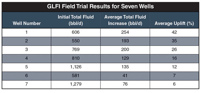
Strong Results
A significant production increase was observed for most of the trial wells. An added benefit was decreased slugging on wells where the bottom-hole pressure exceeded the bubble point pressure. Table 1 summarizes the field trial results for the seven wells for which data was available. Applying GLFI resulted in a 30% average increase in total fluid production, ranging between 25 and 137 bbl/d.
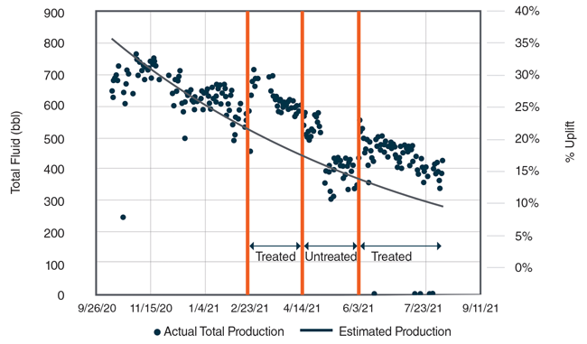
Figure 1 is a production summary for the primary well studied during the field trial using an estimated decline curve provided by the operator. The lift gas injection rate and all other process variables were held constant during the trial. Compared with production with gas injection alone, this well produced 20% more total fluid on average while treating with GLFI.
FIGURE 1
Primary Field Trial Well Production Summary
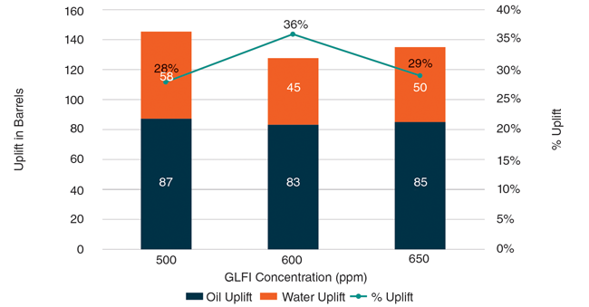
The amount of GLFI injected into the well was varied between 500 and 650 ppm. The corresponding production increase reached as high as 36%.
To confirm GLFI injection was responsible for the positive production response, the chemical was turned off. This resulted in a sharp decrease in total fluid output, with the well’s output soon returning to the estimated decline curve trend. GLFI injection was resumed, and production again increased to above the decline curve (Figure 2).
FIGURE 2
Primary Field Trial Well’s Production
After Beginning, Halting and Resuming GLFI Treatment
The financial benefits as measured by the return on investment were calculated based on the chemical cost versus the monetary gain from increased fluids production from the primary well. This calculation is a non-GAAP financial measure and was based on a conservative oil price of only $30/bbl. Applying GLFI at a concentration of 500 ppm was found to be the optimal dosage, resulting in a 1,025% ROI.
Even at the highest tested rate of 650 ppm of GLFI, the ROI was 750%. Although the financial calculations do not include revenue from gas sales, increased gas production also was observed on the primary well.
As these field results underscore, when integrated as part of a cross-functional solution encompassing the downhole tool design, the chemical delivery method, and automated chemical and gas injection rate controls, chemical packages qualified for the job at hand can help operators get the most out of their wells while ensuring long-term, trouble-free gas lift system operation.

DAVID GILMORE is product line manager and sales manager for gas lift solutions at ChampionX Artificial Lift, focused on gas lift engineering and design through the company’s PCS Ferguson business unit. Based in Houston, Gilmore has 23 years of gas lift experience, serving in technical, operations, sales and management roles at Continental Specialties, Dynamic Lift, Superior Energy Services and Endurance Energy before joining ChampionX. He holds a B.S. from Lamar University.

LUCAS MCKERNAN is an area manager for ChampionX Chemical Technologies focused on production chemistry programs across the Permian Basin. Based in Midland, he joined ChampionX in 2013 as a district representative in the Eagle Ford Shale. During his 11 years with the company, McKernan has executed chemical management programs in midstream, production, completion and water applications in multiple onshore regions in Texas and offshore in the Gulf of Mexico. He holds a B.S. from Texas Tech University.
For other great articles about exploration, drilling, completions and production, subscribe to The American Oil & Gas Reporter and bookmark www.aogr.com.