


Tough Equipment And Robust Automation Improve Artificial Lift Efficiency
By Colter Cookson
In a quest to reduce lifting costs and maximize production potential, operators, equipment manufacturers and service companies are challenging traditional assumptions about when and where each artificial lift technique should be used. By leveraging advances in materials science, automation and engineering, they are expanding the application windows for artificial lift equipment and techniques.
This drive to redefine boundaries is alive and well in the world of gas lift, says Matt Young, director of sales for Flowco Production Solutions. “We typically advise against using gas lift on wells with a gas-to-liquid ratio below 500 to 1, but operators are pushing the limits on what wells can be considered gas lift candidates,” he remarks. “With the right surface controls and feedback from downhole pressure and temperature gauges, the ratio can be much lower.”
Wells with low GLRs usually require more gas injection, Young notes. As a case in point, he cites a pad in the Joe Mills formation of West Texas that had a GLR around 500 to 1. “The operator wanted to bring the wells on line with gas lift rather than electric submersible pumps,” he relates. “When we modeled the system for gas lift, we concluded we could achieve flowing bottom-hole pressures comparable to an ESP by significantly increasing the GLR through gas injection.”
The models suggested that the well would require more than 1 million cubic feet a day, Young details. He says the operator confirmed the gas lift system’s effectiveness by installing a downhole pressure and temperature gauge to track bottom-hole flowing pressure.
“Historically, downhole pressure and temperature gauges have been costly and complex enough to be unreliable,” Young acknowledges. “However, that is quickly changing as technology improves. In only a few years, the cost for downhole gauges has fallen 50% or 60%.”
Meanwhile, the reliability has leaped forward, Young says. “That is largely thanks to improvements in manufacturing and equipment technology, as well as the work automation groups have put into developing drivers that streamline setup,” he explains. “Today, installing the gauges is comparable to pulling a new cell phone out of the box. The technician plugs the system in, turns it on and follows basic setups provided by the driver.”
The downhole gauges can help engineering teams do more, Young reports. “They cut down on troubleshooting and optimization time,” he clarifies. “With the information from the gauge, engineers can understand multiphase flow and hydraulics more quickly. Depending on the other information available, that can save two-four hours of modeling time.”
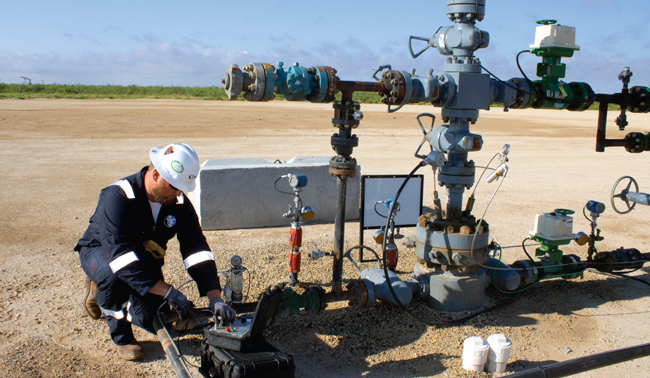
The application window for gas lift is expanding thanks in part to more affordable downhole sensors and automation systems that are easier to deploy, reports Flowco Production Solutions. The company adds that it is refining equipment to support high-pressure gas lift, which can handle high initial production rates.
Enabling Automation
The gauges also give control systems greater insight into downhole conditions, Young adds. “Based on the readings from the downhole gauge, these systems can open and close chokes to increase or decrease the injection rate,” he describes. “They can almost operate a well autonomously, which frees artificial lift engineers to focus on other tasks.”
SCADA systems have come a long way, Young reflects. “The cloud-based systems available today are much easier to deploy and generally more reliable than the radio-based systems of old,” he says. “Most are designed for bandwidth-constrained environments and have a mobile-first interface, which enables them to give engineers a real-time snapshot of the well wherever they happen to be.”
Despite automation’s many benefits, Young says it can make engineers uncomfortable. “Many are reluctant to relinquish control to an optimization program,” he explains. “When we see that reluctance, we recommend configuring automation systems to suggest changes and request authorization rather than operating independently. This approach allows the system to simplify tasks for the engineer without taking away control.”
As costs for downhole gauges continue to fall, Young predicts that many operators will transition from installing one gauge in gas lift wells to several. “By placing gauges throughout the string, operators will be able to track hydraulics from any given depth within the wellbore,” he envisions. “This setup eventually will become as affordable as a single gauge now.
“These gauges will help track multiphase flow, which is tricky to model,” he says. “The reason is that even the vertical sections of a horizontal well are highly deviated. Add in the buckling and curvature in the production tubing, and as produced fluids travel from the horizontal section to the surface, they change directions frequently. The chaotic flow path holds up liquid to varying degrees throughout the production tubing, which leads to inconsistent production at surface.”
In other words, the well may make 1,000 barrels on Monday, 900 on Tuesday and 1,200 on Wednesday. “Today, we can only catch up to that unstable flow because we only know it’s happening when we see the erratic production at surface,” Young says. “If we had multiple gauges throughout the tubing string collecting data at different points, we could identify liquid holdup almost instantaneously and make proactive adjustments before we see it at surface.”
To support more proactive and frequent gas lift optimization, Young expresses hope the industry eventually will adopt electronic gas lift valves that can be opened and closed from the surface. “This would give operators ultimate control over the point from which they want to lift and the operating pressure going to the electronic system, but at least for now, the electronic valves are too expensive and unreliable for widespread use,” he says. “Over time, the reliability and cost should improve.”
High-Pressure Gas Lift
In the short term, Young says the biggest gas lift innovation is high-pressure gas lift, which involves injecting gas at pressures as great as 5,000 psi. “These high pressures have changed the game for gas lift,” Young reflects. “In many wells, they enable operators to produce at rates normally associated with an ESP while benefiting from gas lift’s reliability.”
According to Young, a typical gas lift system can last three-five years before requiring a workover. He says the growing popularity of HPGL has spurred improvements to surface facilities and downhole components.
For example, Young reports that Flowco has created gas lift valves with higher pressure ratings. “By changing the valves’ design and geometry, we were able to get the rating to 2,500 psi,” he details. “Once we were comfortable with the design changes, we began looking at valve materials. Replacing stainless steel or Monel with Inconel-like metals can push operating pressures above 3,000 psi, giving operators confidence the valves will operate with the expected run life under high pressures.”
Instead of injecting gas down the tubing/casing annulus and commingling the gas with the produced fluids inside the production tubing, HPGL wells generally begin with annular flow. The high-pressure gas comes down the tubing and comingles with the production fluids in the tubing/casing annulus, Young describes. He explains that the larger space in the tubing/casing annulus enables greater output. “In some cases, flowing up the annulus can deliver even more production than an ESP,” he reports. “I have seen wells where gas lift increased wells’ initial production by 800 barrels.”
As pressures decline and production falls, annular flow becomes inefficient and the well must transition to producing up the tubing, Young says. “Operators and service companies have come up with creative ways to set up equipment so the transition from annular flow to tubing flow is easy,” he praises. “It can be as simple as running slickline or changing surface valves, which eliminates the need for a workover rig.”
High-Volume Rod Lift
Using larger pumping units can allow rod pumps to handle volumes that traditionally have been restricted to other forms of artificial lift, says Trey Binford, director of product management for beam pumping units at LUFKIN Industries. “Long-stroke beam pumping units can produce as much as 1,000 barrels of fluid a day in unconventional wells,” he reports. “In many applications, this capability can enable operators to move away from ESPs earlier or even start the well on a rod pump.”
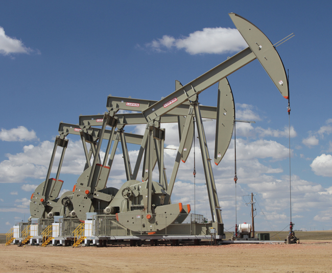
Long-stroke beam pumping units, which now include conventional designs with a maximum stroke length of 320 inches, lift large volumes with slow strokes that reduce wear. In many unconventional plays, LUFKIN Industries says this capability reduces costs by speeding wells’ transition to rod lift.
Broadening rod pumps’ application windows can be extremely helpful, Binford assesses. “Reducing the number of times operators need to bring in equipment and crews to change from one form of artificial lift to the next shrinks capital costs,” he observes. “Rod lift operating costs also are lower than those of ESPs because rod lift requires fewer workovers and less energy, and most operators are so familiar with rod lift that it’s easy for them to optimize and troubleshoot.”
In the past, Binford says, rod lift was rarely considered for unconventional wells until production dropped below 400 bbl/d of liquid because of the stress horizontals placed on the rod string and tubing. “Large pumping units address that durability concern by enabling long, slow strokes that minimize wear on the rod and tubing but still lift high fluid volumes,” he assures.
To enable longer strokes, Binford says LUFKIN has introduced the industry’s largest conventional beam pumping unit. The unit’s maximum stroke length is 320 inches, but it can be configured for stroke lengths of 275 inches, 234 inches or 193 inches, he describes.
At the top of the stroke, the unit is 55 feet tall, equivalent to a four- or five-story building. The horsehead alone is 26 feet long, Binford notes. Because the pumping unit uses a conventional design rather than a linear one, he adds, it allows workovers to be performed without rolling it back.
“All these units are sold with LUFKIN’s full automation package, including a controller and variable speed drive,” he mentions. “This system collects data and analyzes it to slow down or speed up at the right times to optimize the unit and achieve the operator’s objectives.”
So far, the huge pumping units have been deployed in California, the Rocky Mountains and the Permian, Binford reports. “The results have been great,” he says. “One customer wanted to transition from ESPs to rod pumps; we were targeting 500 bbl/d of fluid but ended up getting close to 700 bbl/d. The operator was thrilled because transitioning to rod lift reduced workover and energy costs while maintaining production.”
In a shallower field, the large pumping unit enabled an operator to start a well on rod lift by handling more than 1,000 bbl/d of fluid, Binford continues. “The operators who have deployed a handful of these large units are committing to more,” he says. “They want to try bringing the cost savings and familiarity the units provide to other applications.”
Plunger Lift Reliability
The maximum volume plungers can lift is rising, says Brent Cope, product line manager for plunger lift at PCS Ferguson, a business unit of ChampionX Artificial Lift. “Twenty years ago, plungers would usually max out at 100 bbl/d,” he recalls. “Today, we have plungers moving 500 bbl/d in wells with high gas-to-oil ratios.”
That increase comes in part from continuous bypass plungers, which allow the plunger to fall against flow rates and therefore cycle more frequently. “Depending on well depth, the plunger may make 80-100 trips a day rather than the 10 with an older, nonbypass design,” Cope says. “Each trip carries smaller loads, but the production is more consistent and the plunger can get flowing bottom-hole pressures even lower.”
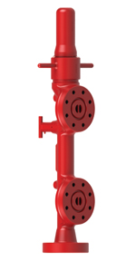
PCS Ferguson, a business unit of ChampionX Artificial Lift, has developed a lubricator that is 100% forged. According to PCS Ferguson, this approach eliminates the weak points associated with welds and produces a consistent metallurgical grain structure that improves the lubricators’ strength, ductility and impact resistance.
As plungers make more trips at higher speeds, equipment durability becomes increasingly important, Cope suggests. He says PCS Ferguson has spent the last year and a half conducting tests to determine which components of a plunger lift system need improvement in various applications. “For example, with bumper springs, we wanted to find out whether the spring, the flow cage or the fish neck would be the primary restriction on durability,” he says.
In some applications, the company now recommends titanium fish necks. “Titanium can withstand much higher impacts than even stainless steel or carbon 4140,” Cope says. “We also use longer springs to increase impact resilience.”
PCS Ferguson has developed lubricators that are forged rather than welded, Cope continues. “We run X-rays and other tools to verify the welds on our lubricators, but over several years, stress can fracture the welds. The forged lubricator takes that concern away,” he explains.
He points out that the forged lubricators are rated to 5,000 psi. “Many companies now use 5,000 psi lubricators by default,” he says. “Whether the lubricators are forged or welded, the higher rating offers peace of mind they will be able to withstand the resulting pressures if a nearby fracture communicates with the well.”
PCS Ferguson’s lubricators include a patented poly spring that can withstand speeds as high as 3,000 feet a minute, well beyond what it should encounter during actual well operations, Cope says. “Over time, springs can weaken and compress,” he reports. “With the spring no longer as effective at cushioning impacts, the plunger contacts the metal at higher speeds and can be damaged. The poly spring helps prevent that.
“We have also gone from dome-style lubricator caps to inspectable caps,” he continues. “With the older style, all the lubricator’s internal components were inside the cap, which meant technicians had to dismantle the cap completely if they wanted to check or work on the spring and anvil. With the new caps, everything is in discrete pieces. Once the cap is off, the technician can see the spring and anvils and easily pop them out of the lubricator if they need work.”
The redesign has lightened the cap, Cope adds. He points out that this reduces the risk of injury when technicians are removing the cap from the lubricator and setting it down, or lifting it to put it back on.
To help operators minimize gas emissions, Cope mentions that PCS Ferguson is partnering with an electronic company to develop a more affordable electronic actuator for auto catchers. “A traditional electronic valve would be too expensive to deploy in an auto catcher,” he says. “Getting rid of unnecessary capabilities and doing some clever engineering makes the cost more competitive.”
Cope predicts that the electronic valve will be available within six months. “We already have electronic valves on the plunger lift system’s sale side, so once the auto catcher valves are introduced, the system will be almost emission free,” he says.
Boosting Gas Production
Liquid loading can significantly reduce wells’ profitability, notes Herman Artinian, president and chief executive officer of Upwing Energy. “When liquid accumulates in the well, it creates blockages and backpressure that reduce gas velocity, which decreases production and may lead to premature abandonment,” he says.
To address liquid loading, Upwing has developed a subsurface compression system that raises gas velocities enough for the gas to carry the liquids to surface. In field trials and simulations, this technology has increased gas production at least 20% and as much as 200%, Artinian reports. He adds that it increases condensate production.
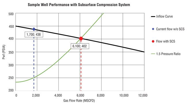
By accelerating gas so it has the velocity to lift liquid blockages to the surface, Upwing Energy says its subsurface compression system improves production from natural gas wells. In field trials and simulations, the production uplift has ranged from 20% to 200%.
Getting a compressor to survive down hole takes ingenuity, Artinian acknowledges. “For durability, the compressor is hermetically sealed,” he describes. “It is driven by a permanent magnetic motor that transfers energy to the compressor through a shaftless magnetic coupling. Since torque travels to the compressor with no mechanical shaft or seals, there is no need to isolate the motor from downhole fluids using a motor protector.”
Motor protectors are one of the most common points of failure for conventional ESPs, so eliminating them should extend the system’s run life, Artinian says.
Like ESPs, the subsurface compression system can be deployed by hanging it from production tubing. “We designed it to support alternative deployment methods as well,” Artinian comments. “For offshore installations, we are looking at using a cable to deploy the system through the production tubing. This approach will reduce installation times and costs significantly, as well as avoid downtime.”
To help busy operators deploy and benefit from subsurface compression, Artinian says the company has launched an end-to-end service. “For operators who use this service, Upwing takes on responsibility for the total process of producing gas, from initial analysis and predictions all the way through to operations and monitoring,” he says. “We become the operator’s single point of contact for the equipment, operations and data.”
According to Artinian, this model emerged from the company’s experience working with operators during consultations and field trials. He explains that these experiences highlighted the value of close collaboration between suppliers and operators throughout a project’s life.
“Operators want to produce more gas from existing assets in an environmentally responsible way,” Artinian says. “With this model, we can take the lead on accomplishing that important goal for our clients while removing the capital and resource constraints they would otherwise face.”
The service starts with an analysis and prediction phase, during which the company evaluates how subsurface compression will impact production dynamics and the reservoir, Artinian outlines. Using this data, Upwing then takes the lead in developing detailed plans for configuration, safety and all other required planning, and oversees all aspects of deployment and startup. Once installed, Artinian continues, the company’s remote communication and control system monitors real-time data from the compressor to optimize its performance.
Artinian stresses that this service model enables operators to boost natural gas production without increasing emissions. He points out that Upwing has been independently certified as a carbon neutral company under the Publicly Available Specification 2060 standard.
“So far, the model has been well-received,” he reports. “We are actively engaged in field trials in the United States, and we expect to be able to announce results in the coming months. Also, we are in the process of securing trials in the Middle East, South America and Europe, where there is high demand for our services.”
Jet Pumps’ Ascent
Interest in jet pumps has been growing, observes Matthew James, co-president of JJ Tech (J&J Technical Services LLC). “We have the ability to install our jet pump far down into the curve or lateral without worrying about pump reliability, which is a huge advantage in horizontal wells,” he explains. “Jet pumps also handle sand well, and depending on bottom-hole pressure, they can lift a ton of fluid.”
In some applications, the pumps can produce 3,000-4,000 barrels of total fluid a day, reports Chris Lamberth, the company’s other co-president. “I have seen daily production as high as 4,500 barrels,” he says. “Because the pumps can handle such high volumes, many operators use them to clean out a well during initial flowback, when sand makes operating an ESP impractical.”
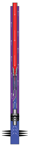
Jet pumps frequently reduce workover costs in harsh environments, including sandy, high-volume wells, because they have no moving parts down hole, JJ Tech (J&J Technical Services) reports. In a standard jet pump configuration, power fluid (red) is injected into the tubing down to the nozzle. The resulting pressure drop across the nozzle allows produced fluid (blue) to enter the jet pump and, ultimately, the mixing chamber, where it combines with the power fluid. The mixture exits the pump and flows to the surface through the casing, JJ Tech describes.
Once the jet pump has removed most of the sand, operators have used the company’s jet pump to size an ESP, a rod lift system, or another permanent form of artificial lift. For more problematic wells, the jet pump may stay on location long past the initial cleanup, James says. “Our jet pump system typically is used for production volumes above 30-50 barrels of total fluid per day, but when bottom-hole pressure lowers to below 200 psi, most operators will implement another form of artificial lift, which is generally a rod pump.” he remarks.
Jet pumps’ initial costs may equal or sometimes exceed those of other artificial lift methods, James says, but jet pumping almost always reduces lease operating expenses in crooked, sandy or corrosive wells simply by reducing the need for workovers. “All the jet pump system’s moving parts are at the surface,” he explains. “The downhole components are very durable and it’s not uncommon for our jet pump system to last three, four or five years in situations where an ESP or rod pumped-well may need to be worked over every six months to a year.”
According to James, the biggest advantage JJ Tech’s jet pump system has over traditional designs is the surface pump. “We use a positive displacement diaphragm pump manufactured by Wanner Engineering,” he says. “Wanner Engineering’s pump has a seal-less design that eliminates the need for lubricating plungers and replacing worn packing, which greatly reduces maintenance and lease operating expenses. Our surface pumps also protect the environment by removing any risk of packing failing and causing a spill.”
The diaphragm pump’s leak-free operation, tolerance for abrasives and low operating costs have made it a favorite choice for saltwater disposal wells and waterflood injection wells, James comments.
In jet pump applications, the surface pump injects produced water or oil (called power fluid) at high pressure, typically into the production tubing. When the power fluid reaches the jet pump, it encounters a nozzle. This restriction causes the fluid to accelerate and create a pressure drop inside the jet pump. This pressure drop allows formation fluid to enter the jet pump. As the power fluid and produced fluid flow through the pump, the combined fluids regain pressure and travel to the surface, typically up the casing.
Since fluid is flowing through all the tubulars within the completion, the tubing and casing can be treated continuously for corrosion, bacteria and other contaminants that might reduce the life of the completion, James points out.
In some extreme cases, especially highly corrosive wells, the jet pump system can be set up in a “reverse flow” configuration. This method allows for clean or treated power fluid to be injected into the casing annulus and the combined fluids produce up the tubing. James says this approach reduces or eliminates damage to the cemented casing and directs any possible corrosion damage to the tubing string (which is replaceable).
If any jet pump components need to be repaired or replaced, the pump can be retrieved simply by reverse circulating it to surface, James adds.
Maximizing jet pumps’ performance requires properly sizing the nozzle and throat, which are the key components for any installation, Lamberth notes. “To optimize the jet pump assembly and ensure our systems run as efficiently as possible, we have developed user-friendly software that evaluates all possible nozzle and throat combinations available, every time a simulation is performed,” he says.
“The program also lets us quickly determine whether a jet pump system is the right choice for a specific well,” he adds. “When it’s not a viable option for a particular application, we recommend another form of artificial lift.”
JJ Tech’s jet pump systems can be purchased or leased, Lamberth points out. “The leases usually include an option to purchase,” he mentions. “Although jet pumps have been around for a long time, they are uncommon enough to be new to many artificial lift engineers. Our lease/purchase option lets those engineers see how effective a jet pump system can be before committing to purchase the system.”
For other great articles about exploration, drilling, completions and production, subscribe to The American Oil & Gas Reporter and bookmark www.aogr.com.