


Advanced Measurements Reduce NPT On ERD Wells
By Daan Veeningen
HOUSTON–Extended-reach drilling seeks to reach a larger area from one surface drilling location and to maximize the well bore’s exposure to the productive reservoir interval. However, the challenges associated with ERD include hole cleaning, managing the mechanical loads on the drill string, and managing downhole pressures.
Historically, extended-reach wells offshore Trinidad & Tobago were characterized by well bore instability and hole cleaning challenges. These phenomena had become almost impossible to manage effectively in the highest-angle well bores, leading to levels of nonproductive time (NPT) that threatened the economic viability of the wells.
Well bore instability exacerbated the hole cleaning challenge, fueled by a new instability mechanism at the highest well bore inclinations. This led to pack-offs and stuck pipe incidents. Additionally, poorly understood and generally insufficient hole cleaning practices increased stuck pipe risk and caused the equivalent circulating density (ECD) to rise, resulting in mud losses resulting from the narrow window between the mud density required for well bore stability and the formation fracture gradient.
The solution to these problems was found through advanced downhole measurements of bore hole stability and hole cleaning, transmitting those data back to surface through a high-frequency medium (networked, or “wired” drill pipe), deploying subject matter experts onto the rig team for critical phases of the operation, and introducing unconventional drilling and decision-making practices to mitigate the problem phenomena.
The multiwell development drilling program targets sands in the Chachalaca complex and is located on the East Shelf of Trinidad, eight kilometers from the Mahogany Field. The field is situated on a regional northeast-to-southwest ridge and bisected by regional growth faults that separate the Mahogany/Chachalaca sub-basin from the Corallita/Lantana discovery, approximately three kilometers to the east. The field consists of multiple stacked pay sands across multiple northwest-to-southeast trending normal faults that dip to the northeast.
FIGURE 1
Directional Profile and Drilling Envelope for Multiwell ERD Campaign
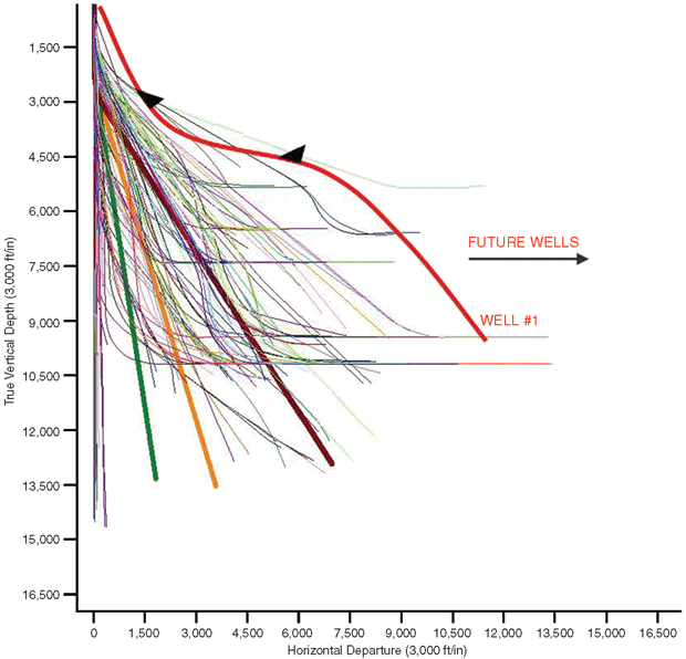
As the Trinidad & Tobago multiwell campaign developed, the wells were drilled at higher inclination, extending the step out beyond 10,000 feet. (Figure 1) shows the directional profile and drilling envelope for the first well and future wells in the multiwell ERD campaign. Operations in both fields frequently suffered from well bore instability and hole cleaning difficulties, especially around multiple problematic zones associated with faults.
Notably, in certain formations, the well bore instability mechanism changed as inclination increased. And well bore instability and hole cleaning fueled each other; as well bore instability caused breakouts, the hole cleaning challenge increased. The inability to sufficiently clean the hole led to increased ECD, which frequently resulted in fluid losses. These difficulties became even more punishing as the drilling envelope was extended.
Operational risks include stuck pipe and the inability to get casing to bottom. The inefficiencies include time to condition the hole and mud, frequent trips, reaming out of the hole and curing losses to the formation. The trouble time (approaching half the productive time) was threatening the economic viability of the campaign.
Well Bore Instability
Figure 2 describes the situation in the left hand of the figure. Subsurface formation properties, stress regime and well bore orientation are key factors in defining the safe mud weight window, or the region in which well bore stability is maintained (“situation”). This safe mud weight window should be controlled under both static and dynamic hydrostatic pressure conditions. Naturally, the flow rate, rate of penetration, well configuration, string rotation and drilling practices are operational aspects that impact dynamic pressures. Drilling practices such as pumping sweeps to aid hole cleaning and back-reaming procedures help manage the dynamic conditions and ECD (“controls”).
FIGURE 2
Interaction Between Well Bore Instability and Hole Cleaning
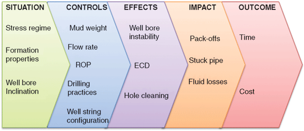
Well bore instability can be observed at the shale shakers in the form of cavings (volumes and shapes), and downhole by analyzing high-definition well bore image logs. Breakouts fuel the hole cleaning challenge as cavings load up the annulus. With insufficient hole cleaning, the ECD increases.
The rising ECD or dynamic pressure can exceed the safe mud weight operating envelope. When this happens, fluid losses to the formation are the result. Operationally, stuck pipe events may occur through insufficient hole cleaning that may pack off the drill string. Conditioning the fluids and treating for fluid losses causes additional trouble time (“impact”).
The overall outcome is increased rig time consumption for establishing the appropriate mud weight to stay within the safe mud weight window, to condition the drilling fluid and the well bore, and to manage ECD. Direct cost results from fluid losses, components lost in hole and even drilling a sidetrack by losing the hole or failing to run casing entirely to bottom (“outcome”). All of these consequences occurred on the project in question, generating 47 and 48 percent NPT, respectively, on the first two wells.
Of particular relevance to the drilling campaigns in the interaction between in situ properties and drilling success was the high angle to bedding that occurred in drilling the long 12¼-inch diameter hole tangent sections of the wells. Multiple faults were typically crossed while drilling this hole section. Formation dip angle and dip direction varied considerably between individual fault blocks, such that an advantageous bore hole attack angle relative to bedding could change quickly to an unfavorable direction on crossing a fault.
When drilling at high angle, conventional bore hole instability (caused by insufficient mud weight to counteract induced bore hole stress concentrations) occurs at the sides of the bore hole. However, in layered shaly formations, an additional mode of instability has been recognized, caused by delamination of the rock fabric.
This bedding-related mode of instability typically is characterized by failure of the roof (i.e., high side) of the bore hole. Low-side failure also occurs, although these cavings often may not be removed from the bore hole and so are not detected as readily as failures on the high side of the bore hole. This mode of instability may occur when drilling within 20 degrees of the bedding-parallel direction.
LWD Techniques
Logging-while-drilling techniques have been developed to identify these different modes of instability that may develop while drilling. Previous applications of real-time imaging have had to rely on mud-pulse telemetry and memory images to inform drilling decisions. There is both a data quality and data availability constraint that can limit the effectiveness of this approach to impact operations in real time. It was for these reasons that networked drill string telemetry was considered for resolving the drilling challenges offshore Trinidad.
Other subtleties existed in the bore hole stability challenges faced while drilling these high-angle wells. The “roof collapse” mode of instability was associated with certain, but not all, formations. Additionally, this mode of instability did not occur in all wells intersecting these problematic formations at high angle, even when at similar attack angles to bedding. Relative bore hole orientation (updip, cross-dip or downdip) certainly played a role in triggering instability, as some trajectories were more susceptible to failure than others.
This is most clearly demonstrated in the predictions of required mud weight as a function of well trajectory shown in Figure 3. The formation properties used are typical of those existing locally. In this figure, the required mud weights are shown as a function of well trajectory in the conventional “dartboard plot.” A vertical well plots at the bull’s-eye, a horizontal well drilled to the north plots at the 12 o’clock position, and a horizontal well drilled to the west plots at the 9 o’clock position, etc. Concentric circles show deviations of 30 and 60 degrees, with the circumference at 90 degrees deviation.
FIGURE 3
Mud Weight Predictions as Function of Well Trajectory
(with and without Bedding-Related Instability)
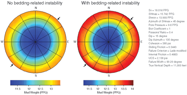
The required mud weights are color-coded on these plots (both plots use the same color scale bar range for mud weight). The left-hand plot shows the required mud weight for uniform formation strength (i.e., no bedding-related effects). The right-hand plot shows required mud weights where bedding-related instability occurs. South-easterly trajectories are drilled downdip, north-westerly trajectories are drilled updip, and north-easterly and south-westerly directions are drilled cross-dip.
The impact of bedding-related instability is seen clearly by comparing the two plots. Where this mode of instability is absent, high-angle wells can be drilled with a mud weight of 13.3 pounds/gallon with little variation in well azimuth. This mud weight is achievable with care relative to the 14.0 ppg fracture gradient predicted for this formation.
Typically, the section would be drilled with a 13.0 ppg equivalent static density (ESD) and 13.7 ppg ECD. Where bedding-related instability occurs, required mud weight in the least-favorable downdip direction is up to 0.7 ppg higher than for uniform formation strength. Here, required mud weights approach (or in some cases exceed) the available fracture gradient.
In this situation, it is impractical to “err on the side of caution” by assuming that bedding-related instability occurs, and to drill with the higher mud weight, since the risk of losses is greatly increased. Rather, it is important to understand when bedding-related instability occurs and only to weight up in response to direct evidence of this. Weighting up at the onset of this instability is required to suppress its full development, as recovery from this mode of instability can be very difficult to achieve.
Once detected, ECD management becomes a key focus for completing the hole section. Therefore, detecting the onset of instability and discerning its mode became a primary challenge for the successful completion of the ERD drilling campaign.
Campaign Objectives
The objectives defined for the Trinidad & Tobago ERD campaign included:
- Managing well bore instability, improving hole cleaning, reducing trouble time and remaining within authority for expenditure;
- Reducing lost circulation events and minimizing fluid loss and associated trouble time;
- Improving downhole tool longevity and eliminating trips;
- Saving time on “critical path” operations;
- Improving well placement and reserve capture;
- Better well control and safety; and
- Eliminating unplanned sidetracks.
People, processes and technology were all critical in the methodology for reducing well bore instability-related trouble time on the Trinidad & Tobago project, but three technologies were particularly instrumental: high-resolution downhole data acquisition, high-speed telemetry of downhole data, and along-string annular pressure evaluation.
With the overarching goal to reduce well bore instability-related trouble time, it was paramount to select the right downhole log measurements to provide insight into the well bore instability mechanisms, and to control the phenomena that caused the well bore instability-related trouble time. Data acquisition was critical during execution (drilling the well) as well as for planning subsequent wells.
LWD was identified as the primary data acquisition means, and would be supplemented only with wireline data at last resort. Real-time, memory-quality data, especially azimuthal density and gamma ray well bore image logs, were critical for understanding the prevailing well bore instability mechanism and identifying bedding-related instability. In addition, it was pertinent to understand stress directions and magnitude in the high-inclination well bores. These insights were obtained through efficient time-lapse logging with azimuthal density and gamma ray image logs in high definition.
High bandwidth downhole telemetry was required to deliver in real time the high-definition downhole data, and to transmit the additional annular pressure measurements for ECD management.
Broadband Drill String Network
Broadband drill string network technology was selected because it provides telemetry three magnitudes higher than wireless telemetry, such as mud pulse. With an available data rate of 57,600 bauds per second for downhole measurements, its transmission is double the number of data points in quadruple the number of sectors (16 sectors) at five times the logging rate (320 feet/hour), compared with mud pulse telemetry. In addition, 57,600 bps of bandwidth is available for transmission of along-string annular pressure measurements.
The networked drill string system consists of three major components: a stainless steel-armored coaxial cable running from pin to box for each tubular, induction coils at both the pin and the box of each connection, and electronic booster subs, which prevent the data signal from degrading as it travels the length of the pipe and provide pressure/temperature measurements all along the drill string. Data are transmitted by means of an electromagnetic (EM) field associated with the alternating current signal transmitted along the cable. As the alternating EM field from one coil induces an alternating current signal in the nearby coil, data are transmitted from one joint of the drill pipe to the next.
FIGURE 4
Temperature and Annular Pressure at Six Network Nodes
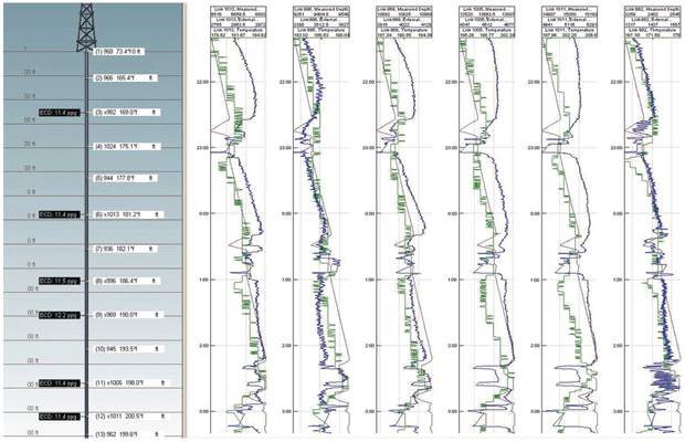
Operational benefits are gained by high-frequency vibration measurements that allow for minimizing shocks and vibrations to downhole tools, which increases tool and bit longevity. Furthermore, reduced shock results in more effective energy transfer to the bit with higher resulting penetration rates. In addition, networked drill string technology provides data from downhole tools even when the pumps are off to make measurements during static conditions. Finally, mud pulse as a redundant telemetry system is available and serves as a fallback during instances where the networked drill string data transmission is unavailable.
The networked drill string uniquely provides the means to identify and analyze the annular pressure at discrete points along the drill string (i.e., at each network node, typically spaced 1,500 feet apart). The along-string annular pressure evaluation capability is available during static conditions for identifying ESD and better managing ECD during dynamic conditions. Figure 4 displays along-string temperature and annular pressure measurements at six discrete network nodes for a typical well profile during the campaign.
People And Processes
It was decided to bring experts to the rig instead of the alternative of taking the data to experts to eliminate potential delays in decision making and execution, especially with the various team members located in different time zones around the world. For the Trinidad implementation, the on-site experts included well bore stability experts to monitor well bore quality in real time, drilling engineers tasked with monitoring the hole cleaning efficiency through the annular pressure sensors distributed along the drill string and to optimize sensor placement, and experts to assist in introducing the technology and developing new workflows.
It was important to forge tight team involvement within the customer’s organization. Local drilling management drove the integration of new data and expert skills into decision making. The service companies providing directional drilling, downhole data acquisition, drilling fluid and telemetry services were involved in prejob planning and detailed operational planning during execution.
The tight involvement allowed relevant experts to interpret and understand the downhole phenomena and the operations team to refine its practices to regain control of deteriorating well bore conditions. This significantly reduced problem time. The ability of subsurface teams to utilize high-quality images proved of major importance in updating subsurface models while drilling the well.
Process improvement through the right people and technology was vital in delivering a transformational reduction in well bore instability-related trouble time, as evidenced in specific drilling practices such as sweeps.
As commonly practiced, weighted sweeps were pumped for hole cleaning, but now the effectiveness was evaluated through the along-string annular pressure measurements independent from surface observations. Downhole measurements led to an increase in frequency for pumping sweeps, with sweeps pumped in tandem. In practice, while one sweep was in the annulus, the second sweep was already pumped.
FIGURE 5
Along-String Annular Pressure Measurements
Showing Weighted Sweep Lifting Cuttings
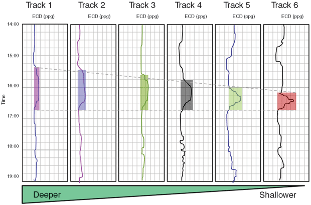
Figure 5 illustrates a weighted sweep traveling up the annulus and being detected at each of the six annular pressure measurement nodes. The figure demonstrates that the location of the sweep can be identified and tracked as it travels up the annulus by the annular pressure measurement at each of the network measurement nodes. The arrival time at each measurement node provides an estimate for the average hole size between measurement nodes.
The along-string pressure evaluation helped determine the required flow rate for hole cleaning, and for the first time, actual cutting removal and cavings efficiency could be measured directly, and hole cleaning practices could be adjusted to maximize efficiency. In addition, actual friction losses in the annulus could be compared with modeled losses, cuttings loading in the annulus could be determined through the pressure measurements in the annulus and compared with the bore pressure readings, and cement volumes could be determined for accurate cement top positioning.
Time-Lapse Logging
Formation image logs were used to identify well bore deterioration by comparing images captured at different times. Subsequently, this insight was used to optimize the required mud weight to stabilize the well bore. Specifically, bedding-plane instability mechanisms could be identified using time-lapsed logs of high-definition well bore images early enough to respond with an immediate mud weight change early enough in each section to maintain the overall bore hole condition.
FIGURE 6
Well Bore Instability Analysis through Breakout Identification and Time Dependency using Azimuthal Density Imaging while Drilling (Left)
And Relogging Six Hours Later (Right)
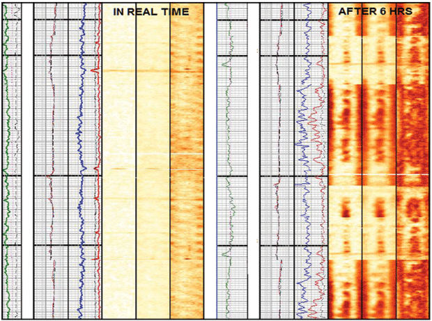
The images in Figure 6 show azimuthal density data binned into 16 sectors (each sector covers a 22.5-degree arc) to create a density image. The images, shown in groups of three, represent the bulk density image on the left, the long-spaced image (center), and the short-spaced image on the right. Lower density (e.g., drilling fluid and breakouts) are represented by dark colors, with formation highlighted by the lighter colors. The images are oriented relative to the bore hole geometry. For display purposes, the cylindrical hole is cut down the axis of the hole (along the top) and “unwrapped.” The top of the hole lies on the far left- and right-hand sides of the unwrapped image, and the bottom of the hole (180 degrees from the top of the hole) is in the center of the image.
The light colors shown in the “as drilled” real-time image show the bore hole to be in-gauge at the time of drilling. However, after six hours of exposure, the dark colors seen in the short-based image (less than two inches in depth of reading) indicate bore hole enlargement. The enlargement is more uniform in the top half of the image and is only slightly rotated from the top-bottom orientation in the lower half of the image. The long-based image (shown in the center of the three images) has a depth of investigation of three to five inches.
Remembering the top-sides/bottom-sides/top unwrapping convention in the image, the long-based sensor more clearly shows that some roughly top-bottom enlargement has occurred in this well out to several inches beyond the as-drilled bore hole diameter. The small rotation of the enlargement (about 15 degrees) from the true top-bottom orientation indicates that this is breakout and not key-seating in the well.
As mentioned, conventional breakouts arising from insufficient mud weight occur on the sides of the bore hole in high-angle wells. However, this image indicates that instability is occurring on the high and low sides of the bore hole (the small rotation of breakouts from the top-bottom orientation arises from the well bore being drilled in a direction that is misaligned with the prevailing in situ stress directions). This image shows that the more problematic roof collapse mode of instability is occurring and that prompt weight-up corrective measures are required. This requires both an increase in mud weight and to more proactively manage hole cleaning.
Had the breakouts been oriented on the sides of the bore hole only, then a period of more diligent attention to hole cleaning only would be required. In this way, the memory-quality bore hole images transmitted in real time were key to correctly diagnosing the mode of bore hole instability and implementing the appropriate remediation measures.
‘Wait-And-Weight’
The time-lapse methodology provided the data acquisition component in the “wait-and-weight” process.
With a fracture gradient of 14 ppg, mud weights between 13.0 and 13.5 ppg (depending on bedding-related instability) were selected for these high-angle well bores and fine-tuned as drilling. The casing and a few hundred feet of formation were drilled with the initial mud weight, and a high-definition well bore image log was acquired. Next, the drill string was pulled back into the casing shoe while the section was relogged. The time-lapsed logging was analyzed for signs of well bore deterioration. If required, the mud weight was adjusted before drilling continued. This process was repeated periodically to ensure the optimum mud weight was selected.
During drilling, the ECD was managed carefully to stay within the safe mud weight window to prevent losses or well bore collapse (it led to loss of hole sections on the first two wells). The controls to manage ECD while drilling include adjusting ROP and fluid rheology, in addition to mud weight selection and sweep strategy, to carefully quantify the ECD effect. These processes transformed hole conditions on the third well and the liner was ran to bottom with no problem.
The viability of this development project was transformed by a combination of new technology, the involvement and field deployment of world-class subject matter experts, and amended drilling practices. This combination transformed ERD efficiency by allowing problem mechanisms to be properly diagnosed, from which appropriate curative methods could be attempted, interpreted, refined and made successful, all within one hole section. This approach is a model for future ERD campaigns in areas where high-well-bore inclination or formation characteristics, or both, introduce well bore instability and hole cleaning problems.
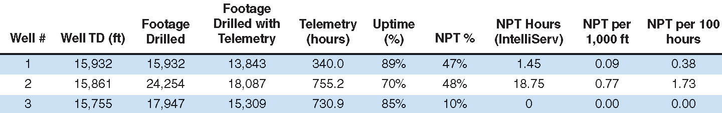
More generally, the approach of relying on comprehensive measurements and experts to provide accurate diagnosis of downhole phenomena, followed by their assistance to the rig team in improving practices, has validity more widely in drilling and completions activity. The summary of the transformational performance improvement and system reliability is presented in Table 1. Well bore instability NPT was reduced from 47 and 48 percent, respectively, on the first two wells to 10 percent on the third well, and trouble time was limited to rig equipment.
TABLE 1
ERD Performance Summary
Daan VeeniNgen is director of marketing at NOV IntelliServ, where he is responsible for global marketing of the broadbrand networking and along- string evaluation services for high-definition downhole and surface operations. He previously served as business development manager at NOV IntelliServ. With 15 years of oil field experience, Veeningen holds patents on numerous oil- and gas-related technologies. Before joining NOV in 2008, he served for 11 years at Schlumberger in a variety of positions spanning real-time operations, well engineering and drilling. He holds a master’s in petroleum engineering from Delft University of Technology.
For other great articles about exploration, drilling, completions and production, subscribe to The American Oil & Gas Reporter and bookmark www.aogr.com.