


Artificial Lift Systems
Guidelines Help Operators Select Artificial Lift Systems For Deliquefying Gas Wells
By Cleon Dunham, James F. Lea and Greg Stephenson
HOUSTON–Natural gas wells are often thought of as free flowing with no need for artificial lift. However, many gas wells produce some liquids–condensate, water or both–at some stage in their life cycles. If this liquid is not removed from the well, it will accumulate in the well bore, inhibit gas production and limit the ultimate recovery of gas from the reservoir.
The accumulation of liquid in the well bore causes increased pressure against the producing gas formation (back pressure), which inhibits gas flow from the reservoir into the well bore. This back pressure also inhibits gas flow up the well bore to the surface. The liquid in the well bore also can enter the reservoir and cause a water blockage that will further inhibit gas flow into the well.
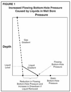
Figure 1 illustrates increased flowing bottom-hole pressure caused by the presence of liquid in the well bore.
Therefore, to maximize gas inflow and outflow, and to maximize ultimate recovery from the reservoir, it is necessary to remove any accumulated liquid from the well bore and keep it removed on a continuous basis.
Figure 1 illustrates increased flowing bottom-hole pressure caused by the presence of liquid in the well bore. Artificial lift reverses the process of liquid loading and the resulting back pressure that leads to reduced reservoir inflow from inhibited gas flow to the surface. By lowering the bottom-hole pressure, artificial lift encourages gas inflow and the “drying” of the formation.
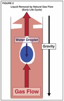
Figure 2 - In the early stages of a gas well’s life cycle, liquid may be removed by the natural flow of the gas itself.
In the earlier stages of a gas well’s life cycle, liquid may be removed by the natural flow of the gas itself (Figure 2). If the flow rate is high enough, the gas flow velocity may exceed the “critical” velocity. When the velocity is above critical, the liquid that is present is carried to the surface by the gas in the form of mist or small droplets.
However, as reservoir pressure declines with age, inflow performance declines with formation blockage, or the amount of liquid increases, the natural gas flow velocity may fall below critical so that liquids can no longer be removed from the well on a continuous basis. At this stage, some form of artificial lift is needed to remove liquids from the well and the near-wellbore portion of the reservoir.
Artificial Lift Methods
At least 15 artificial lift methods are used by operators to deliquefy gas wells. They include:
- Sucker rod pumping;
- Progressing cavity pumping;
- Electrical submersible pumping;
- Hydraulic pumping;
- Tubing plungers;
- Casing plungers;
- Soap sticks;
- Batch chemical;
- Continuous chemical;
- Velocity strings;
- Surface compression;
- Continuous gas lift;
- Intermittent gas lift;
- Vortex flow; and
- Liquid injection.
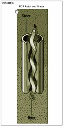
Progressing cavity pumping has the advantage that it is not easily gas locked, since the pumping process is based on a continuous movement of the pump rotor in the stator (Figure 3)
If gas wells produce significant amounts of liquid, conventional sucker rod pumping can be used. Here, a challenge is to prevent the gas from interfering with the pumping action. Typical strategies include setting the pump intake below the perforated intervals and/or using an effective form of gas separation below the pump intake. In such cases, liquids are typically pumped up the tubing and gas is allowed to flow up the tubing-casing annulus.
Progressing cavity pumping has the advantage that it is not easily gas locked, since the pumping process is based on a continuous movement of the pump rotor in the stator (Figure 3). However, PCPs have three main limitations in gas deliquefication applications.
First, many pumps, particularly high-volume models, have limited head capacity, so depth of application is often limited. Second, PCPs cannot withstand high temperatures since the pump stators contain elastomers that continue to cure and become brittle at high temperature. In addition, stator elastomers are generally sensitive to aromatic content and cannot be run in the presence of high-API gravity fluids such as condensates. For these reasons, they cannot be set too deep or allowed to pump off to a “run dry” state, and they can be run only in wells where produced fluids are compatible with the elastomers.
Electrical submersible pumping is used when large volumes of liquid (normally water) must be produced. ESP’s advantage is the ability to lift large volumes of liquid from deep wells. ESPs may become gas locked, so using downhole gas separators or some form of pump-off control may be necessary. And, the ESP motor must be cooled since high temperature can damage the motor windings. Therefore, there must be sufficient flow of liquid past the motor to keep it cool. In many cases, this prevents operators from being able to set the pump below the perforations, unless some form of pump shroud is used.
There are two types of hydraulic pumping systems: open systems where the injected fluid to operate the pump is commingled with the produced fluid at the pump, and closed systems where the injected fluid is kept separate from the produced fluid and returned to the surface through a separate flow path. Because of its complexity, hydraulic pumping is seldom used for gas well deliquefication, although some new designs are being tried in the industry.
Plungers And Chemicals
There are several types of tubing plungers, but the primary types are single- and two-stage. For single-stage plungers, production from the well must be stopped to allow the plunger to fall and sufficient pressure to build to lift the plunger back to the surface. For two-stage plungers, shut-in time can be kept to a minimum since the plunger ball and body fall separately. The primary advantage of tubing plungers is that no external source of energy is needed. The plunger is lifted to the surface–along with any accumulated liquid above the plunger–by the natural pressure of the well. The primary limitation is that they may not be able to work when reservoir pressure falls to a very low level, so they may not be able to fully deplete the gas reserves in the reservoir.
Casing plungers are used in wells with no tubing. They work on a similar principle, except there is no annulus for pressure to accumulate to lift the plunger. Pressure must build up below the plunger.
Soap sticks are used to mix with the liquid in the well to create a foam that is much lighter than the native liquid. The foam can be produced from the well by the natural flow of the gas. The primary advantage is low cost, and they can be used when a well first experiences liquid loading, without the need to install an expensive artificial lift system. The limitations are the cyclic nature of dropping soak sticks, and in some cases, the difficulty in reaching the full depth of the well.
When dropping soak sticks is insufficient, chemicals can be injected into the well in batches. The principle is the same, in that the chemical mixes with the liquid in the well bore to form a foam that is produced by the gas. The limitations are that it is cyclic in nature, and that different chemicals are needed for water and condensate.
An alternative to cyclic injection is continuous injection of chemical through a capillary string. The advantages are that the chemical is injected continuously and can be injected at the desired depth. The limitation is that the flowing gas must lift the foamy liquid.
Velocity Strings
As indicated, liquid will be removed from the well by natural gas flow if the velocity is above critical. Since velocity is a function of the gas flow rate and the cross-sectional area of the flow path, reducing the cross-sectional area increases velocity. Often, wells are initially completed with a large tubing size to allow high gas production rates. As the rate decreases with pressure decline and other factors, it may be possible to sustain critical velocity by installing a smaller tubing size, or by producing up the annulus between the original tubing and a smaller insert string. The disadvantage is that this may work for a given set of conditions, but no longer work when conditions change.
Many operators install surface compression systems. Compression may allow a well to be operated with a lower wellhead pressure since the gas pressure is boosted so it will flow from the wellhead to the production facility. The lower wellhead pressure may translate to a lower bottom-hole pressure, thereby permitting increased inflow. Also, the lower pressure may result in a lower critical velocity to allow the well to produce liquids longer in its life.
Continuous gas lift can be used to inject gas into the well near or below the perforated interval. The added gas can lift the liquid to the surface and provide additional gas flow so critical velocity is maintained. In principle, gas lift can be used to fully deplete a well if the correct amount of gas can be injected at the correct depth.
An alternative to continuous gas lift is intermittent gas lift where “slugs” of gas are injected to produce slugs of liquid. In oil wells, intermittent gas lift is normally used in lower-rate wells or wells with low bottom-hole pressures. In gas wells, intermittent gas lift may make more sense in wells that produce more liquids, since the primary objective is to remove liquid and not to maintain critical flow at all times.
The concept with vortex flow is to introduce vortices in the flowing gas stream that better carry the liquid droplets to the surface. The liquid is swirled to the outside of the tubing, leaving gas and droplets to flow in the tubing. This is a relatively new, largely untried technique. Design techniques are being developed.
The liquid injection injects water into an underlying zone and allows gas to migrate up the casing. Pumps may be involved, but no liquid is produced to the surface.
Developing The Guidelines
The guidelines for selecting the most appropriate artificial lift system are being developed on a Web site supported by the Artificial Lift Research & Development Council (http://www.alrdc.com). There is a Web page for artificial lift selection for gas well deliquefication (click on “recommendations”). Anyone may access this site to see the progress being made and use the materials as they are drafted and placed on the site.
The method(s) of dissemination are yet to be determined, but once the guidelines are completed, they may be disseminated to the industry in a variety of ways, including on the Internet, in a book or notebook, in workshops and seminars, and in general or company-specific training courses.
The first section contains guidelines to be followed by operating companies, service companies and others responsible for creating an optimum artificial lift selection process for their organizations. A number of issues can have a substantial impact on selecting the “best” form of artificial lift, and guidelines can be different for operating companies and service companies, domestic versus international operations, and for onshore versus offshore operations. In addition, company size can be important, as can the history and culture of corporate operations.
Economics are also a consideration. Some companies focus on maximizing revenues, some on minimizing capital costs, and some on minimizing operating costs. Still others are more concerned with safety and environmental protection than with either income or costs. Moreover, some companies have personnel who understand and can work effectively with some forms of artificial lift, but not others. If an artificial lift system is not well understood, operated and maintained, it may fail.
Also, some forms of artificial lift may not be available in some locations. If suppliers are not available to provide and help install and maintain artificial lift equipment, it may fail. Reservoir characteristics, well depth, tubular size, hole deviation, production type, flow rates, well performance and the surface system and equipment also can have an impact on guidelines.
Other Sections
The second section presents the fundamentals of gas well deliquefication, including how to recognize when liquid loading is beginning to occur, and how to calculate the critical velocity needed to lift liquids from a well. It contains general guidelines for all 15 forms of artificial lift, and each set of guidelines for each type of artificial lift is being developed by a team of industry experts.
The guidelines include practical limits of each type of artificial lift (depth, size, pressure, temperature, rates, sand, corrosion, erosion, hydrogen sulfide, carbon dioxide, etc.), power requirements, operating and maintenance requirements, cost guidelines (CAPEX, OPEX, and repair and maintenance), and life expectancy guidelines.
The third section contains guidelines to be followed to select the most appropriate artificial lift system for a given field. This includes pertinent issues that must be considered when selecting the most appropriate artificial lift system for a particular field; using the various artificial lift selection tools and tables developed in the industry; evaluating capital, operating and repair/maintenance costs of various artificial lift options; selecting an artificial lift system supplier; and choosing a specific artificial lift system for each well in each field.
Finally, the fourth section contains guidelines to be followed once the artificial lift system has been selected. These include recommended guidelines for installation, operation and maintenance over the long term, which are essential to successfully using an artificial lift system for effective gas well deliquefication. They also cover automation, surveillance and optimization issues, all of which have become essential to the profitable use of artificial lift systems, as well as training operating company personnel to take maximum advantage of specific artificial systems.
Editor’s Note: Industry experts from a variety of companies have volunteered to help prepare the guidelines for selecting artificial lift systems for gas well deliquefication. Some sections have been fully drafted, while work continues on other sections. Anyone interested in joining the team and helping draft the guidelines can contact Cleon Dunham at the Artificial Lift Research & Development Council, 512-732-0545 or e-mail cleon@oilfieldautomation.com. The preceding article was adapted from a presentation originally prepared for the 2008 Southwestern Petroleum Short Course.

CLEON DUNHAM is president of Oilfield Automation Consulting in San Antonio, focusing on oil and gas production automation and artificial lift. He is also secretary of the Artificial Lift Research & Development Council. Dunham is retired from Shell Oil Co. after a 36-year career in facility engineering, reservoir engineering, production engineering and computer control engineering, with a primary focus on production automation and artificial lift. He spent the past five years of his career with Shell International E&P in The Hague, Netherlands, where he helped coordinate Shell’s worldwide production automation and artificial lift activities. He is a member of work groups of both the American Petroleum Institute and International Standards Organization for writing standards and recommended practices for gas lift. Dunham holds a B.S. in engineering from Cornell University.

JAMES F. LEA, Ph.D., is the Roy Butler professor at the petroleum engineering department of Texas Tech University. He previously served as the department chair. Before joining Texas Tech, Lea was the team leader of production optimization and artificial lift at amoco EPTG in Tulsa, where he was employed for 21 years. Lea received the 1996 SPE International Production Award, as well as the J.C. Schlonneger Award from the Southwestern Petroleum Short Course for his contributions to artificial lift. He is the author of “Artificial Lift Completions,” of “Petroleum Well Construction,” and is a co-author of “Gas Well Deliquefication.” Lea has served on Society of Petroleum Engineers’ committees related to artificial lift, and has twice been an SPE distinguished lecturer.

GREG STEPHENSON is the product line manager for artificial lift optimization at Weatherford International. In this position, he directs and administers the overall product strategy for optimizing of artificial lift systems, including marketing, business development, engineering development and commercializing of new hardware and software products. Stephenson has more than a decade of experience specializing in the areas of production engineering, design and optimizing artificial lift systems, completions engineering, automation, training and product line management. He holds a B.S. in petroleum engineering from Texas Tech University.
For other great articles about exploration, drilling, completions and production, subscribe to The American Oil & Gas Reporter and bookmark www.aogr.com.