


Drilling Fluids Technology
New Solutions, Practices Redefining Cutting-Edge In Fluids Technology
By Ryen Caenn
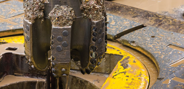
LAGUNA BEACH, CA.–Drilling fluids technology and best practices continue to evolve in step with the industry’s relentless quest to optimize drilling performance in all types of geology, operating environments and wellbore geometries.
Fluids technologists are using specially engineered chemistries to create advanced systems that are handled carefully from start to finish and disposed of in safe and environmentally acceptable manners. The latest innovations include designer chemistries, total solids and waste control, and perhaps most importantly, automated control of the mud system on the well site.
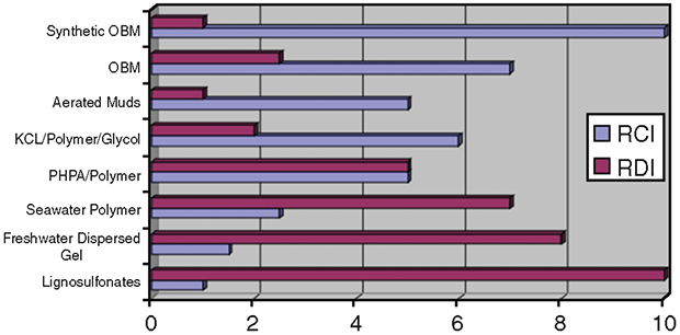
FIGURE 1
Relative Mud Cost Index
Versus Relative Damage Index
Fluid system selection should be guided primarily by the geology of the formations to be drilled, with each hole section potentially requiring its own fluid and additives. Geologic considerations include producing zone characteristics; geothermal gradients; shale reactivity; and the presence of surface clays and sand, tectonically altered structures, and salts. Drilling operations must also be taken into account, as horizontal wellbores require a different type of fluid than do straight holes drilled through the same sections.
In today’s cost-conscious industry, cost per barrel is obviously a key consideration in selecting the best fluid option. However, a mud system’s cost per barrel can be very misleading unless all cost factors are considered, and deciding on the wrong fluid can be a very costly mistake. Figure 1 shows the relationship between the cost index and the relative damage of eight fluid types, with the cheapest mud causing the most damage to the producing zone. While more complex fluid systems cost more, they may eliminate potential drilling problems that could turn into major nonproductive time (NPT) events.
Base Fluid Systems
The chemistry of any drilling fluid depends on the base fluid used for its construction–pneumatic, water or oil–and sets the chemistry of all the additives used in the system. Figure 2 shows the various systems for each base fluid.
FIGURE 2
Types of Drilling Fluid System
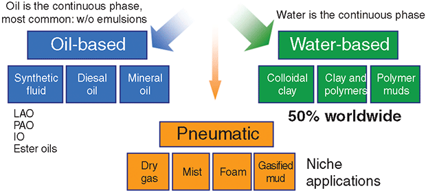
Only a small percentage of wells are drilled pneumatically. The wells always are drilled underbalanced and have the advantage of fast drill rates and minimal damage to the producing zone. Pure compressed air is circulated through the bit at high volumetric rates and cuttings are ejected as dust. If increasing amounts of formation water are encountered, the air system is converted to mist or foam. A number of horizontal wells have been drilled pneumatically in the Marcellus Shale, and some operators are using hybrid pneumatic systems (inject air into the mud) for managed pressure drilling.
The base fluids for water-based products range from freshwater (chloride content below 5,000 milligrams/liter) to saturated brines. Brine-based systems typically eliminate the need to use bentonite for viscosity and fluid loss control, and API mud properties are controlled by various types of water-dispersible polymers.
In offshore drilling, cost and logistics dictate using seawater as the preferred makeup fluid in top-hole drilling, and perhaps down to intermediate pipe setting. With seawater salinity and salt makeup varying throughout the world, the trend has been to use more brine fluids to formulate the mud. Freshwater “wets” shale formations and can accelerate wellbore collapse, depending on the characteristics of the shale formation. Brine-based systems, along with a variety of shale stabilizing additives, slow the water wetting of shales to delay associated wellbore stability problems.
Another reason for using brine-based systems is to minimize excessive solids buildup in the mud, which is related to most drilling fluid problems in water systems. These mud problems include lower penetration rates, bit balling, and contamination issues such as high gel strengths and excessive circulating pressure drops. Brine water inhibits the hydration of clays in the shale. Some brines, depending on the cation present, are better than others for wellbore stability.
FIGURE 3
Maximum Densities for Various Brine Solutions
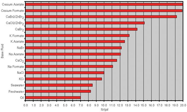
While drilled solids are “bad” solids and high density-weight materials such as barite are “good” solids, all solids can contribute to contamination problems and high pressure drops that cause high equivalent circulating densities (ECDs). Saturated brines can be used in place of mineral-weight materials such as barite in many drilling operations. The majority of wells seldom require mud weights higher than 14 pounds per gallon. Figure 3 shows the maximum densities at saturation that can be obtained with a variety of brines versus pure water and oil.
Using brines to control mud weight (up to salt saturation) and/or clay inhibition (3 percent to saturation) are part of the makeup of “enhanced” or “high-performance” WBMs, especially for wellbore stabilizing with water-based drilling fluids.
Two types of brines are being used to formulate water-based fluids: inorganic brines, primarily based on chlorides; and organic brines, primarily based on formates. One of the advantages of using a formate brine is in waste disposal, such as land farming cuttings. Formates will degrade into carbon dioxide and water. Chlorides, on the other hand, cannot be removed chemically, but must be diluted to acceptable regulatory levels.
Nonaqueous Systems
All nonaqueous drilling fluids (NADFs) are based on some type of liquid, which from a chemistry standpoint, is an oil (diesel, mineral oil or synthetic). Environmentally acceptable, nonaqueous drilling fluids are the fluid of choice for deepwater drilling operations around the world. The International Association of Oil & Gas Producers (IOGP) classifies NADFs into three categories:
- Group 1 (diesel and conventional mineral oils);
- Group 2 (low-toxicity mineral oils); and
- Group 3 (synthetics and highly refined paraffins).
These three groups were developed based on the relative marine organism toxicity and the biodegradation of the fluids. Whether a particular base fluid can be used is subject to local regulatory agencies, but according to IOGP statistics, 55 percent of offshore operations in international waters use Group 3, 26 percent use Group 2, and 19 percent use Group 1 NADFs.
Diesel and conventional mineral oil are banned in U.S. federal waters and are tightly regulated elsewhere around the world since they contain aromatic compounds that can be toxic to marine organisms. For the most part, they are relegated to onshore work where hazardous waste sites are available or where regulations permit land farming for cuttings disposal.
Synthetic NADFs, and in some cases low-toxicity mineral oil, are the fluid of choice for most offshore drilling. In deepwater operations, drilling fluids are constructed exclusively with a synthetic-base fluid, typically an olefin with a carbon chain length of 14-18. Another type of synthetic is esterified vegetable oil, primarily from palm oil. Synthetics are preferred because they can eliminate wellbore stability problems relating to shale water-wetting, thereby minimizing NPT.
Wellbore Stability
FIGURE 4
Wellbore Pressure Differential and Stability Issues
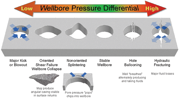
There are many mechanisms involved in wellbore stability, including unconsolidated formations, tectonic stresses, abnormal pore pressures, and swelling clays in shales. In any case, the first line of defense is to have the proper mud weight (Figure 4). The vast majority of formation footage drilled is through some type of shale containing various types of clays. Some clays are very active (swell) and some are not. It is well established that NADFs can eliminate wellbore instability caused by clay swelling. The primary mechanism for this is the osmotic control of water flow from the mud to the formation and vice versa. The correct mud weight must also be in place.
FIGURE 5A
Water Invasion in Water-Wet Wellbore
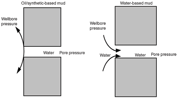
One way an NADF enhances wellbore stability is by making the wellbore completely oil-wet. A water-wet wellbore allows water invasion as a result of capillary action (Figure 5A). Calcium chloride (CaCl2) is the most common additive for osmotic flow control (Figure 5B) in NADFs. CaCl2 imparts a very low activity in the water phase, thereby producing the largest osmotic pressure driving force.
As noted, chlorides may cause additional waste management costs, depending on local disposal rules. An ongoing line of research is to find materials with low water activities that can replace the chlorides. Additives that have been tried include formates and acetates, calcium nitrate, and many types of polyols.
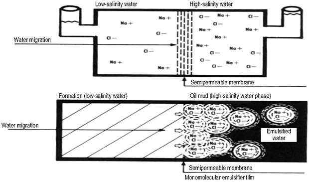
FIGURE 5B
NADF Osmotic Flow Control using Calcium Chloride
Because of high rig day rates in deepwater drilling operations, the practice is to use a synthetic oil to allow the cuttings to be dropped overboard. NADFs can be up to five or six times the cost per barrel of a water-based system, but their ability to improve wellbore stability makes them cost-effective by eliminating NPT. In applications where day rates are lower, high-performance WBMs can be much more cost effective than NADFs.
NADF Mechanism
Although the newer generations of high-performance WBMs have improved well stabilization compared with WBMs, they can only slow the imbibition of water. By delaying clay swelling, however, these fluids can buy enough time so that casing can be set to protect the wellbore. High-performance WBMs need a number of additives to minimize water imbibition into shales. In addition to having the proper mud weight, additives reduce the shale’s permeability by plugging the tiny pore openings in shale formations. Additives also may be needed to plug any natural fractures in steeply dipped formations.
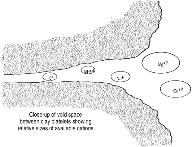
FIGURE 6
Clay Fixation using K+ Cation
A generic list of some of the additives used includes products for osmotic control, clay fixation, accretion control, membrane/film formation, and pore/fracture plugging. Osmotic control is not as critical in WBMs as in NADFs, but some water activity control is needed, and it usually is accomplished by using either organic or inorganic brines.
Clay fixation usually is done by the cation associated with the brine. The most effective cation is the potassium ion (K+). The hydrated size of the K+ ion seems to be the best size to fit into the pore openings of most shales (Figure 6).
Accretion control additives are surfactants similar to the materials used to control bit balling. They are normally co-polymers of amid or amine compounds with fatty acids. These materials physically attach to the clays, blocking free water from the clays.
NADFs work so well because they form a semipermeable membrane on the wellbore, allowing for the osmotic transfer of water. The fluids industry has not yet been able to construct this type of membrane or film formation in a WBM. Instead, WBMs form a “leaky” membrane, which is still important because it reduces the shale’s pore openings and minimizes the capillary action that occurs when water contacts a shale (Figure 7).
FIGURE 7
‘Leaky’ Membrane Formed with WBM
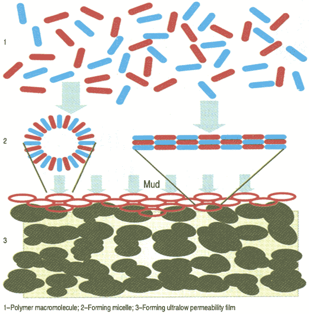
Most drilling fluid polymers are film formers to some extent, but partially-hydrolyzed-polyacrylamide is the most common. Another set of chemicals used for film forming are polyols and multihydroxy alcohols, which are very successful and work by hydrogen bonding with the shales.
Plugging materials plug openings in the shales to slow water penetration. Some of the materials used are asphalt products, gilsonites, lignites, graphite, and fibrous cellulose products. A relatively new line of research is focusing on using nanoparticles.
Lost Circulation
FIGURE 8A
Schematic of Wellbore Ballooning
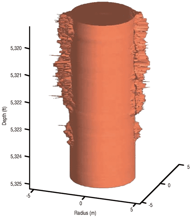
A joint industry project initiated in the 1990s targeting lost circulation and wellbore ballooning has resulted in a much greater understanding of those problems and how to use drilling fluids to strengthen the borehole. Researchers learned there is a difference between WBMs and NADFs in the pressures needed to propagate a fracture once it is initiated. Wellbore ballooning describes the effect of creating a series of microfractures in the wellbore that expand and close in response to ECD (Figure 8A).
The solution is to add bridging agents to the mud system. These small particulates enter a microfracture as it opens, acting to prop it open and plug the microfracture. Then, when pumping stops and ECD is removed, the additives act similar to the keystone of an arch, imparting increased hoop stresses around the wellbore. Figure 8B shows this so-called stress cage theory of wellbore strengthening.
FIGURE 8B
Stress Cage Theory of Wellbore Strengthening
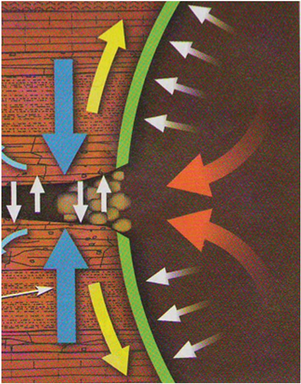
The materials used for wellbore strengthening include deformable graphite, small-sized calcium carbonate, small nut shells, micronized cellulose, and fibers. The materials must be small enough to pass through shale shaker screens since they are carried continuously in the drilling fluid.
The Future of Drilling Fluids
Going forward, drilling fluids research and development likely will focus on several key areas, including:
- High-performance WBMs;
- Solids-free WBMs;
- High-temperature/high-pressure drilling applications;
- Mud testing automation;
- Optimized drilling fluids engineering; and
- Competency assurance.
Work certainly will continue on developing high-performance water-based systems capable of eliminating the use of NADFs. From an operational standpoint, there also will be more use of high-density brines as the base fluids to WBM construction. This likely means increased use of organic brines, such as sodium and potassium formates.
In regard to HP/HT drilling, predictions indicate that pressures to 30,000 psi and temperatures to 600 degrees Fahrenheit will be encountered soon, particularly in subsalt plays such as the Lower Tertiary in the ultradeepwater Gulf of Mexico. No standard NADF or high-performance WBM is completely acceptable at those parameters today, but there is no doubt that the industry will conquer the fluid stability challenges at these ultrahigh pressures and temperatures.
Considerable research is being directed at automated mud testing, and work is in progress to measure the API drilling fluid properties on the rig using devices placed to continuously measure mud weight and a single-point viscosity. There are devices that can measure the rheology of the mud to some degree, but more refinement is needed to be able to more accurately calculate the ECD in the annulus. Devices also are available now to measure solids content and particle size distribution, but they are not continuously automated. The industry continues to investigate continuous chemical analysis and fluid loss measurements.
Going hand-in-hand with testing automation is the ability to continuously automate the varying surface system flow rates, the drilling fluid volumes in the circulating and storage systems, and mud dosages and mixing. Several companies are working on these processes, some in conjunction with various managed pressure drilling techniques and/or early kick detection. A complicating factor is that NADFs have constantly varying viscosities and densities related to the changing temperatures and pressures encountered in the circulating system.
FIGURE 9
Instrumented Surface Measurement
Of Drilling Fluids System
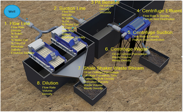
Ideally, it would be best to have downhole sensors, but it is unlikely that these will be readily available or cost effective any time soon. As an alternative, the industry is developing surface or mud line techniques that show more immediate promise for data collection.
From a drilling fluids system standpoint, Figure 9 shows an example of the types of surface measurement and monitoring instrumentation available; in this case a system developed by Zaxxon Instruments LLC. The process uses a system of sensors and programmable logic controller-based software covering the circulating system and all of the solids control equipment. Zaxxon has developed several “drilling fluids data processing modules” that utilize the flow rate, density, mass flow rate and temperature data from Coriolis meters to infer drilling performance characteristics and improve the diagnostic understanding of the system.
These enhanced diagnostic capabilities can be used to quantify the efficiencies of several key performance indicators in the drilling process, including mud pump efficiency calculations, early kick detection, lost circulation severity, hole cleaning efficiency, and sweep efficiency evaluation. These data will enhance solids removal equipment evaluation, dilution economics, hydraulics modeling, wellbore stability, and waste management. Because the new sensors are clamp-on devices, they make rig up very easy compared with the Coriolis meter technology.
Even with all the technological and operational advancements being introduced to drilling practices, arguably the single most important element to ensuring a safe and successful drilling project is the basic competency of the personnel on the rig site. The industry continues to focus on making certain that rigs are equipped not only with the best available technologies, but also well-trained and competent workers.
Verifying competency for all workers on a well location is a difficult proposition, but it is moving forward, especially in well control operations. Each operating and service company has different criteria for verifying competencies, but they all have a vested interest in doing their best both technically and operationally. It is likely that third-party verification will become a requirement at some point for drilling fluids engineers and technologists.
As always, the drilling fluids industry has many challenges before it. Through the years, oil and gas companies, service companies, and drilling fluids technology providers have successfully pulled together to overcome problems encountered both down hole and on the surface. The future will be no different as the industry strives to develop innovative solutions ranging from new materials to control blowouts, additives products to enhance wellbore stability and strengthening, environmental and waste management processes, and engineered systems for extreme HP/HT applications.

RYEN CAENN has 49 years of experience in the drilling and completion fluids industry, beginning his career as a mud engineer at Baroid Drilling Fluids. He has been a member of the API committee on drilling fluid standards since 1974. Specializing in drilling and completion fluid technology transfer, Caenn is principal of TekRite Communications, which has consulted oil companies, fluid service companies and chemical manufacturers in the U.S. and international drilling and production fluids industries since 1981. He is also founder of drillcompfluids.com, a wikibase website that provides the fluids industry with a repository and database to facilitate technology transfer, including new product development and applications. Caenn teaches schools and courses on drilling and completion fluids. He holds a B.A. in chemistry from Oklahoma State University.
For other great articles about exploration, drilling, completions and production, subscribe to The American Oil & Gas Reporter and bookmark www.aogr.com.