


Cascade/Chinook Operations Show STMZ Systems’ Viability In Completing Lower Tertiary Wells
By K. Scott Ogier, Ziad Haddad, Oswaldo M. Moreira, Flavio Dias De Moraes and Jonathan Shipley
HOUSTON–The Cascade/Chinook project in the ultradeepwater Gulf of Mexico involves the joint development of two fields in the Walker Ridge area, 160 miles south of the Louisiana coast. Although these fields are 15 miles apart, they are being developed jointly to optimize the economics of the project using subsea trees, manifolds, free-standing production risers and related subsea equipment tied back to a common floating production, storage, and offloading (FPSO) vessel for field operations, surface separation and processing–the first of its kind in the Gulf of Mexico. The produced oil will be transported to market using shuttle tankers, and the gas will be sold through a gas export line.
At water depths of 8,200-8,900 feet, the Petrobras-operated Cascade/Chinook project is one of the deepest subsea development projects ever carried out. This project will mark the first sustained oil production from the Lower Tertiary formation in the Gulf of Mexico at these depths and pressures. Cascade/Chinook not only marks the first application of an FPSO in the Gulf, but it is also the world’s deepest water depth for an FPSO. The BW Pioneer FPSO is owned by BW Offshore and is contracted to Petrobras, with a design capacity to process 80,000 barrels of oil and 17.6 million cubic feet of gas a day.
The FPSO received first oil production from the Cascade Field in February when the Cascade-4 well, drilled to a depth of 26,200 feet, commenced production.
As part of the initial phase of the Cascade/Chinook development project, Wells A and B (the first wells completed) used single-trip multizone (STMZ) frac-pack completions to provide stimulation and sand control, representing the first STMZ completions in ultradeep water. With gross interval length exceeding 1,000 feet, reservoir pressures greater than 18,500 psi, bottom-hole temperatures higher than 250 degrees Fahrenheit, 26,000-foot true vertical depths, and water depths of up to 8,900 feet, these STMZ completions were the first of their kind.
TABLE 1
Cascade/Chinook Critical Reservoir Properties
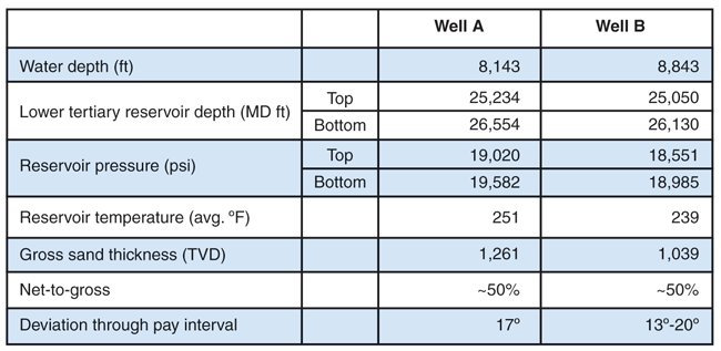
STMZ completions are designed to significantly reduce the rig time required to complete wells with long productive intervals by reducing the number of trips in and out of the well with the work string, compared with conventional stacked frac-pack completions. The pay interval at Cascade/Chinook includes Wilcox 1 and Wilcox 2 Lower Tertiary sands. Table 1 lists some of the critical reservoir properties seen in Wells A and B.
Completing wells at this depth with a large gross reservoir thickness using conventional stacked frac packs would be very time consuming. With operating spread rates in excess of $1 million a day, reducing the time to complete the wells is critical in improving the economics of the project.
A number of completion designs were examined to complete these challenging wells, including stacked frac-packs, open-hole completions, stand-alone screens, natural completions, cased and fractured with no sand control, and horizontal multilateral completions.
Each scenario was analyzed with respect to production deliverability, cost and risk. Ultimately, a STMZ completion technique was selected for Cascade/Chinook because it provides completion engineers great flexibility in designing the frac jobs and minimizes the completion time and cost without sacrificing productivity. It was estimated that a three-zone STMZ completion would reduce the completion time by almost 20 days over a three-zone conventional frac-pack at Cascade/Chinook.
STMZ Completions
With an STMZ completion, all completion intervals in a well are perforated at once, followed by running all the lower completion hardware (screens, sleeves, packers, etc.) into the well and setting the packers. Using an inner work string with shifting collets, a frac sleeve at the top of each interval and a pressure monitoring sleeve at the bottom of the interval are shifted open before the interval is frac packed. By manipulating the sliding sleeves, each interval is opened individually and frac-packed sequentially from the bottom interval to the top. Before moving to the next interval, the sleeves are closed and pressure tested, providing isolation between the well bore and the reservoir. The steps are repeated until all the intervals are stimulated.
FIGURE 1
STMZ Frac and Reverse Operations
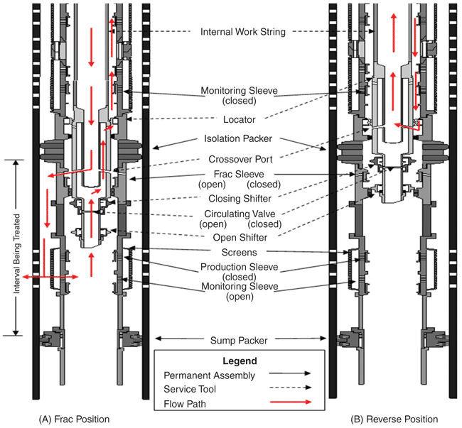
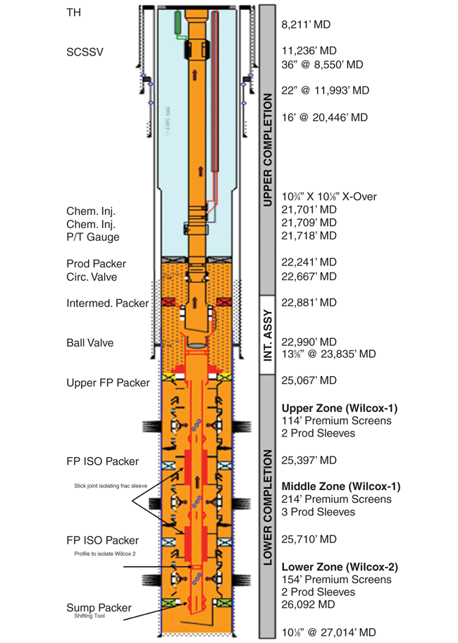
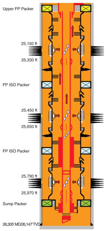
FIGURE 2
Well A Completion Schematic
A STMZ system is a viable option if all the perforated intervals are at approximately the same pressure gradient. The hydrostatic pressure exerted by the completion fluid must be high enough to create an overbalanced environment for all the intervals while reducing excessive fluid loss to the formation.
Figure 1 shows the tool positions for both frac and reverse operations. In the frac position, the monitoring sleeve and the frac sleeve are both opened while the production sleeves remain closed. Weight is applied on the locator to keep the tool in position. Proppant-laden frac fluid is pumped down the work string, through the crossover port and frac sleeve, around the screens, and into the reservoir. There is a path that allows pressure to communicate through the monitoring sleeve and the circulating valve and into the annulus to be monitored at the surface.
An optional squeeze position can be created by leaving the monitoring sleeve closed. In the squeeze position, frac pressure is kept on the outside of the screen assembly. The squeeze position may be necessary if the sump or the annulus cannot withstand frac pressures. Frac pressure cannot be monitored at the surface while the tool is in the squeeze position.
To reverse out the proppant remaining in the work string after the frac operation, the service tool is picked up and placed in the reverse position, closing the frac sleeve and the circulating valve. Completion fluid is pumped down the annulus through the crossover port and up the work string until the returned fluid is free of proppant.
Figure 2 shows the completion schematic of Well A. With the STMZ system, the production sleeves, located in the screen joints (separate from the frac sleeves and the pressure monitoring sleeves), are opened with a shifting tool while deploying the intermediate completion assembly. After the sleeves are opened and the intermediate packer is set and tested, a mechanical ball valve is closed while the work string is retrieved, isolating the reservoir from losses or flowing. The ball valve is hydraulically opened during the final completion commissioning after installing the upper completion (production tubing, packer, SCSSV, etc.) and prior to the rig demobilization.
Sand Control Challenges
The Cascade/Chinook completions present several challenges. First, with a relatively low reservoir fluid mobility and “zero” vertical permeability, fracture stimulation is essential to achieve adequate production rates and a long life. Second, rock-mechanics testing indicates that formation sand production could become an issue as the reservoir depletes, making it necessary to install downhole sand control equipment in the initial completion design. A sand control completion also serves as a means to retain the proppant pack and prevent proppant flow back, which would lead to potential flow assurance issues with the subsea production infrastructure.
Third, the maximum drawdown pressure between the initial reservoir pressure and the final flowing bottom-hole pressure is anticipated to be greater than 12,000 psi. Great care has been taken to ensure a robust design for burst and collapse loads throughout the life of the wells.
Determining the number and length of the perforation intervals in the completions requires detailed fracture modeling, taking into account the lithology of the formation, a detailed multilayer model of the in situ stresses in the field, and the limitations of the downhole hardware. High-strength proppant is required to maintain fracture conductivity under the extremely high formation closure stresses.
The high-strength proppant is especially erosive on the downhole equipment when pumped at frac rates and the downhole hardware must be able to withstand the pumping of all the stimulation treatments. After extensive modeling, flow loop erosion testing and several design modifications, the frac tools were qualified to 1.5 million pounds of proppant pumped at 40 bbl/minute.
Finally, in addition to the requirement of formation isolation for each interval, it was deemed necessary to have the ability to shut off flow from the Wilcox 2 reservoir in the future. An oil/water contact had been identified in the Wilcox 2 reservoir. If this interval begins producing water, a wireline plug can be set in the inner production string below the Wilcox 1 reservoir to shut off flow from the Wilcox 2.
As with any project of this magnitude, significant planning went into designing the completions at Cascade/Chinook. When the decision was made to use the STMZ system, there were a number of system components that needed to be upgraded and qualified for the pressures, pump rates, and depths that would be encountered. The completion team worked closely with the supplier to make the necessary modifications and qualify the STMZ equipment prior to deployment. As a contingency, a conventional stacked frac pack system was prepared.
Planning Issues
Some of the planning issues that were unique to this project and the STMZ systems:
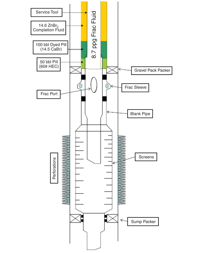
FIGURE 3
Fluid Spotted on Backside to Aid Reverse Out
- The STMZ system requires positioning the service tool in a number of mechanical profiles throughout the completion operation. Locating the correct position at measured depths up to 26,000 feet from a floating rig with subsea blowout preventers is quite a challenge. In each zone, there is only one unique (weight-down) position that is used as a reference point for tool positions. Figure 1 shows the locator in the weight-down position during frac operations.
- When pumping cool fluid down the work string, especially during the frac job at high rates, the contraction of the work string caused by cooling must be taken into account to maintain proper tool position. This was extensively modeled to account for the required weight set down to ensure the tool did not move out of position during pumping.
- The small-diameter (3.22 inches outside diameter) inner work string must fit inside the screen assembly. The inner work string is susceptible to buckling, and this presents difficulty getting weight down on the frac tool to keep it in position while pumping the frac treatment. A great deal of modeling was performed to achieve the best string design and recognize its limitations.
- The number and length of intervals to be fractured was extensively modeled to ensure the most efficient stimulation of the formation. This is a very detailed, log-derived model that considers many layers of rock stresses to evaluate fracture propagation, orientation, height and final fracture conductivity. Although prepared to include as many as five intervals in each well, the team ultimately decided on three intervals in each of the two wells that were completed as the most efficient fracture treatment design. The real-time pressure analysis while pumping indicates a very favorable match. Quality assurance/quality control of the frac fluids is also essential to a successful execution.
- To address the concern of excessive fluid loss while tripping in with the intermediate assembly (Figure 2) to shift open all the production sleeves, modifications were made to the opening profiles of the sleeves. As originally designed, all the production sleeves would have the same profile and the sleeves would open as the shifter on the bottom of the inner production string passed through the screen assembly (a process that could take several hours). The completion design team worked with the supplier to develop a suite of shifting profiles and matching shifters. With this new approach, all the production sleeves open with the running of the last stand of work string, greatly minimizing the amount of fluid lost to the formation and considerably reducing the buckling loads, since most of the inner string is inside of the screen assembly before any of the shifters engages to its corresponding sleeves.
- To ensure that the zinc-bromide (ZnBr2) completion fluid would not be discharged overboard when reversing out after the frac jobs, a nonzinc spacer fluid followed by a viscosified spacer fluid is pumped ahead of the pad fluid. These spacers are placed in the annulus above the downhole equipment before the service tool is placed in the frac position (Figure 3). The viscosified spacer aids in reversing out the remaining proppant after the end of each frac job. Furthermore, the non-zinc spacer is dyed to help visually identify when the spacer is reversed out before flow is diverted to the shakers to capture the ZnBr2 completion fluid.
- The proppant was tagged with radioactive isotopes. The radioactive material in the frac fluid was monitored continuously while the fluid was revered out overboard. There was a clear break in the radioactive tracer counts when all the proppant had been reversed out, indicating the returns were free of any proppant. This was supported by visual confirmation of the dyed, nonzinc spacer that was placed between the proppant-laden fluid and the ZnBr2 completion fluid. Diverting the reversed fluid to the shakers after all the proppant was reversed out overboard ensured that no radioactive material would contaminate the active brine system on the rig.
Nonproductive Time
Table 2 shows the STMZ portion of the completions by major activity for both wells A and B, beginning with the tubing-conveyed perforating operation and continuing through setting the intermediate assembly. The times are broken into trouble-free, nonproductive time (NPT), and total time.
TABLE 2
Breakdown of Completion Times
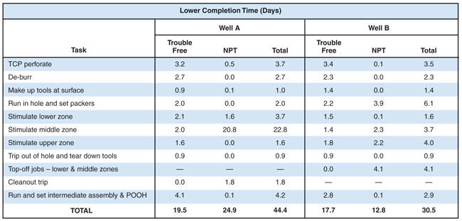
The first significant NPT event occurred while reversing out the work string following the minifrac and step-rate test on the lower zone of well A. While pumping at eight bbl/minute down the annulus (reverse position), only two bbl/minute returns were observed on the surface, indicating high downhole losses. Diagnostics revealed that the monitoring sleeve in the middle zone had inadvertently opened and completion fluid was being pumped into the middle zone.
Reverse circulation was re-established with full returns and the frac job in the lower zone continued as planned. While reversing out after the stimulation, the middle zone monitoring sleeve opened again. The same issue occurred later with the monitoring sleeve in the upper interval.
Analysis led to the suspicion (later confirmed by a laboratory experiment) that if the service tool was picked up too high when reversing, the flow path across the monitoring sleeve became restricted when the upper slick joint was across the sleeve. This unique position induced a piston effect that forced the monitoring sleeve open. One of the contributing factors that led to this unique position was the lack of a positive indication when the service tool was in the reverse position. The optimal reverse position is achieved within a four-foot window, which is quite dynamic and difficult to locate at 26,000 feet.
Great care was used to locate the reverse position after pumping the middle zone frac-pack and no issues were encountered with the upper zone monitoring sleeve. For Well B completion operations, a four-foot spacer pipe was added to the bottom of the screen assembly to increase the length of the reverse position. This, coupled with careful monitoring of the tool position, successfully eliminated the premature opening of sleeves for all subsequent jobs.
The majority of the NPT (20.7 days) associated with the well A STMZ operation was related to the service tool becoming stuck after frac-packing the middle zone and the subsequent fishing operation.
An examination of the recovered service tool revealed the tungsten-carbide erosion ring below the bottom of the crossover tool was missing and that one of the beryllium-copper arms of the closing shifter had broken off. The investigation team believed that the tungsten-carbide ring was likely the primary factor causing the service tool to become stuck. First, the ring broke and then a piece from the ring became lodged in the closing shifter, causing an arm of the shifter to break when it could not flex as designed. As a result, a piece of the broken shifter became wedged between the screen assembly and the service tool, causing it to become stuck.
After the inner work string was recovered, a cleanout trip was made to ensure the inside diameter of the screen assembly was not compromised and a pressure test was performed to confirm the pressure integrity of the STMZ system. For the remaining stimulation treatments (upper zone in Well A and all three zones in Well B), the tungsten-carbide erosion ring was replaced with a less brittle steel ring.
When the crossover tool was recovered after the middle zone frac job, severe erosion was observed below the erosion ring. The portion of the tool that was eroded should have been protected from the slurry. Either the tool was not in the correct position (possibly held out of position by debris associated with the broken erosion ring) or the tool moved during the frac operation. To counteract the thermal contraction of the work string caused by cooling, additional weight was applied to the tool before pumping the treatment, and the work string was slacked off approximately four feet after pumping the pad. Temperature gauges located in the service tool showed a cooling of up to 120 degrees throughout the stimulation treatment.
The largest contributor to NPT in well B completion operations (3.9 days) was related to a pressure leak identified below the sump packer. Because there were open perforations above the sump packer, it could not be determined if the leak was around the elements of the sump packer, across the seal bore of the sump packer, or in the sump area itself. The sump had been tested to 5,800 psi during the casing test prior to perforating. The leak may have been caused by the shock generated with the detonation of the perforating guns.
FIGURE 4
Well B Lower Completion
After determining there would be no mechanical risk to the well bore, the completion operation continued, but fracture stimulations were pumped in the squeeze position to keep pressure off the sump. A small screen assembly was installed in the isolation string to prevent proppant flow back during production, should proppant enter through the sump packer (Figure 4).
Results And Modifications
Although there was a significant amount of NPT associated with the STMZ completions, the completions were ultimately successful, demonstrating the viability of STMZ technology as a completion option for ultradeepwater Lower Tertiary reservoirs with the potential to save significant completion time.
The trouble-free time to install the STMZ system–from picking up the perforating guns through installing the intermediate assembly–averaged 18.6 days for wells A and B. The planned trouble-free time for a conventional three-zone stacked frac-pack to perform a similar operation for a Cascade/Chinook well is 32.8 days. Adding 40 percent NPT for BOP testing, rig maintenance, weather delays, trouble time, etc., the calculated time savings of an STMZ over conventional stacked frac-packs is 19.8 days for a three-zone completion.
Based on the experiences of the first two STMZ completions at Cascade/Chinook, several modifications to the STMZ system are being implemented to reduce risk and improve performance.
The service tool is being extended and an additional set of open/close shifters is being added so that the monitoring sleeve can be closed after stimulating with upward movement only. This reduces risk by eliminating the need to strip into the hole to close the monitoring sleeve. Extending the tool also allows additional pressure/temperature memory gauges to be installed to monitor downhole fluid flow during the frac jobs.
Also, the tungsten-carbide ring design is being replaced with an erosive-resistant material below the crossover port, and several designs are under development to address this new material in addition to changing the crossover tool geometry. The final design will be qualified with an erosion test.
Two other long-term changes are modifying the STMZ equipment to accept intelligent completion equipment to segregate production from the Wilcox 1 and Wilcox 2 reservoirs, and modifying the system to work in open-hole completions to save considerable time and cost by eliminating the need to run, cement and perforate a production liner.
Editor’s Note: The preceding article was adapted from SPE 147313, a technical paper prepared for presentation at the Society of Petroleum Engineer’s Annual Technical Conference & Exhibition, held Oct. 30-Nov. 2 in Denver.
K. SCOTT OGIER is a deepwater completion engineer with Cherokee Offshore Engineering, an engineering consulting firm, and has been working with Petrobras in developing its ultradeepwater Lower Tertiary Gulf of Mexico fields for the past five years. Prior to that, he worked since 1993 developing Gulf fields as both a completion engineer and a production engineer for Devon Energy Corporation. Before coming to the Gulf of Mexico, Ogier worked for seven years in a variety of capacities in the Appalachian Basin for Devon’s predecessor, Pennzoil. He holds a B.S. in petroleum engineering from Texas A&M University and an M.B.A. from St. Bonaventure University.
ZIAD HADDAD established FOI Technologies in 2010 as a deepwater consulting company. Prior to that, he worked for Pennzoil Production Company and Devon Energy Corporation as a well engineering adviser on numerous high-profile domestic and international projects both on- and offshore. He has spent the past 15 years working in designing and implementing all aspects of well completions with emphasis in the field of hydraulic fracturing. Since 2008, Haddad has been working with Petrobras on developing its ultradeepwater Lower Tertiary Cascade/Chinook project. He holds a B.S. in petroleum and natural gas engineering from Pennsylvania State University.
OSWALDO M. MOREIRA is a senior completion engineer at Petrobras with 18 years of experience in the upstream sector. He has worked for Petrobras since 2006 in the integrated project team responsible for planning, implementing and supervising the completion design work for the Cascade and Chinook fields. Moreira holds a B.S. in mechanical engineering from the Rio de Janeiro Federal University (Niterói) and a master’s in business from Rice University.
FLAVIO DIAS DE MORAES is a senior well engineer at Petrobras working on ultradeepwater well drilling and completion design. He has worked as a technical consultant in well completions and material science, and has had several management assignments, including asset well construction manager and well engineering manager at the Petrobras R&D Center. Since 2007, he has served as the well engineering manager for Petrobras America Inc., responsible for the well design for the Cascade and Chinook fields. De Moraes holds a B.S. in mechanical engineering, an M.S. in material science, and earned a Ph.D. in petroleum engineering from the University of Tulsa.
JONATHAN SHIPLEY is at Cherokee Offshore Engineering. Prior to working with Petrobras America Inc., he was the Brazil drilling manager for Devon Energy in Rio de Janeiro. Shipley has held well engineering and management positions with ConocoPhillips, Chevron, Pennzoil and PDVSA, mainly in South America, Africa and the Gulf of Mexico.
For other great articles about exploration, drilling, completions and production, subscribe to The American Oil & Gas Reporter and bookmark www.aogr.com.