


Field Results Offer Insights To Optimizing Transverse Fractures In Liquids-Rich Resource Plays
By Mike Vincent
DENVER–Hydraulic fracturing is the key that has unlocked vast hydrocarbon resources contained in lower-permeability resource plays. More specifically, it is the extensive reservoir connectivity achieved with transverse (perpendicular to the well path) fractures initiated from horizontal laterals that is allowing operators to cost-effectively develop unconventional reservoirs previously considered uneconomic.
Horizontal wells provide the ability to initiate multiple fractures from each well. However, by definition, horizontal wells are drilled into a single reservoir layer, which means they depend on hydraulic fracturing to create conductive and durable fractures to breach permeability barriers throughout the productive interval. Completing horizontal wells in multistage frac treatments to initiate transverse fractures is the most effective means to dramatically increase the extent of the well bore’s contact with the reservoir. In fact, creating multiple transverse fracs from a horizontal lateral can increase reservoir contact by six orders of magnitude, compared with an unstimulated vertical well.
Horizontal wells with transverse fractures are dominating development activity in liquid-rich resource plays such as the Bakken Shale/Three Forks formation in the Williston Basin, the Eagle Ford Shale in Texas, the Niobrara in the Rockies, and the Viking formation in the Western Canada Sedimentary Basin. More “mature” oil resource plays such as the Spraberry, Wolfcamp and Niobrara have been developed for decades with vertical wells, but now are being rejuvenated with horizontal wells drilled between vertical producing wells. Early reports are encouraging that transverse fracturing will allow the economic development of the Mississippian Lime play in Oklahoma and Kansas, the Utica Shale in the Northeast United States, and a number of other emerging tight oil plays.
However, the success to date in stimulating and producing these low-permeability reservoirs with multiple transverse fracs does not imply that the process is optimized. The industry’s experience in designing and implementing transverse fractures in liquid-rich formations remains at an early stage, and significant improvements in well productivity and profitability are anticipated.
Because transverse fractures suffer from an extremely small area of intersection between the well bore and fracture, they are more vulnerable to damage related to inadequate proppant quality, low proppant concentration, overflushing, or proppant flow back. Many low-permeability reservoirs will require decades to recover the contacted reserves, putting more focus on the durability of proppant packs. In addition, liquid-rich formations induce larger pressure losses within the fracture caused by multiphase flow, necessitating more attention to increased fracture conductivity and liquids removal from the fracture system and well bore.
Critical Issues
Field results from liquid-rich resource plays completed with transverse fractures are yielding insights into many critical issues, including whether wells are achieving acceptable vertical height growth, what adjustments may be necessary to accommodate multiphase flow, and the degree of fracture conductivity needed. Field results also are shedding light on how many frac stages are required to provide optimal economic returns, whether each stage is being stimulated effectively, what precautions are necessary to avoid or reduce proppant overflushing, and whether these wells eventually will require restimulation.
There clearly are challenges to accommodating multiphase flow in transverse fractures; establishing best practices in low-permeability liquids-rich resource plays will take time. While the evidence indicates that fractures fail to sustain hydraulic continuity through many laminations, there are techniques available that can improve the ability to drain multiple stacked-pay intervals with horizontal wells. Production results from plays such as the Bakken and Eagle Ford should be of benefit to any operator stimulating horizontal wells that produce significant oil, water or condensate volumes.
In several fields, as many as 40 frac stages in individual wells have been implemented with encouraging results. In other fields, treatment strategies are believed to allow the initiation of multiple fractures within each stage, suggesting that more than 150 transverse fractures have been initiated from some well bores. Obviously, the industry has learned how to touch a lot of rock!
However, despite the resounding success of transversely fractured wells, there are a number of observations that indicate transverse frac treatments have room for improvement. For instance, in some fields, a vertical well with a single frac treatment can outperform a cemented horizontal well in which one identical treatment is pumped from a single set of perforations. Why? The answer is related to two recognized limitations imposed by transverse fractures initiated from horizontal wells: inadequate fracture height and/or hydraulic continuity, and flow convergence caused by limited connectivity between a transverse fracture and the well bore.
Limited Fracture Height
Sedimentary formations were deposited in a near-horizontal orientation, and hydrocarbon-bearing reservoirs generally are composed of sequential layers of sediment. While some of these sediment layers provide relatively high horizontal permeability, they often are draped with mud, silt or other fine-grained materials that introduce permeability barriers between layers.
There are least two consequences of these micro- and macro-laminations. First, formations typically provide extremely low permeability in the vertical direction. Simply put, fluids do not like to travel vertically through many rocks because of a series of permeability barriers. This should not come as a surprise to anyone in the oil and gas industry; if vertical permeability was high, all the generated hydrocarbons would have leaked off long ago, since they are less dense than the surrounding rock and water. The very fact that large amounts of hydrocarbons still remain to be discovered speaks to how robustly the laminae can provide an impermeable barrier to vertical fluid flow.
Second, fractures do not like to grow through laminated sequences. Laminated sequences with varying mechanical properties and alternating degrees of bonded and unbonded surfaces are resistant to fracture penetration. Consider a piece of wood. Lumber is more resistant to splitting “against the grain” than “with the grain,” and plywood is more resistant to fracture penetration than nonlaminated wood. While an imperfect analogy for hydraulic fracturing of highly stressed formations, the development of a crack through wood can demonstrate conceptually that fracture growth can be blunted in laminated reservoirs.
Although folding and uplifting have altered the dip of many reservoirs, horizontal wells usually are steered to remain within a single target layer. Therefore, the well bore only contacts a thin portion of the reservoir, and operators must depend on hydraulic fracturing to contact reserves throughout the vertical pay interval. With the amount of media and political attention alleging unintended fracture height growth and the resulting potential for subsequent contamination of groundwater, one might incorrectly infer that it is easy to generate massive vertical height growth. My experience has been the exact opposite: Fractures often are exceedingly well contained within the interval in which they are initiated.
Especially when considering the stress regime near shallow potable aquifers, where induced fracturing would be expected to be horizontal, it is challenging to imagine a scenario in which a fracture could penetrate multiple bonded and unbonded interfaces to develop appreciable vertical height. Even in deep wells, hydrocarbon production data routinely demonstrate that effective fracture heights can be very restricted.
Fracture Height Growth
The vertical extent of fractures has been evaluated through multiple methods, including incorporating detectable tracers in the fracturing slurry, coring through the created fractures, and physically mining the surrounding rock to directly observe the created fracture geometry. Fracture treating pressure data are routinely evaluated to infer created fracture height, and microseismic and tilt mapping have been used in numerous fields. The combined evidence is very compelling that fracture height is constrained by rock strata.
It has been documented in some reservoirs that fractures can remain so incredibly well contained within the layer of fracture initiation that injected fluids can intersect offset wells perforated at exactly the same depth more than 2,000 feet away in the identical hydrocarbon-bearing interval. If fractures experienced uncontrolled vertical growth, clearly they would not intersect offset wells at this distance, thereby proving containment within the hydrocarbon-bearing interval.
In some reservoirs, fractures are known to grow a short distance into the immediately underlying or overlying formations, and undesirable production of brine from the Ellenberger and Lodgepole formations has been documented from fractures initiated in the adjacent hydrocarbon bearing layers. However, I am unaware of any instances in which a fracture injection treatment has breached reservoir laminations to intersect an adjacent well in anything other than the hydrocarbon-bearing strata immediately adjacent to which the fracture was initiated.
Studies of fracture height growth in aggressive hydraulically induced frac treatments, such as the Mounds injection pilot in Texas, have demonstrated that while sequential injection into a formation can initiate multiple vertical fractures, height was restricted and the created fractures did not experience uncontrolled vertical height growth into shallower and presumably lower-stress intervals.
In many vertical wells, multiple prospective layers are perforated and a single frac treatment is pumped to inject proppant into each perforation cluster. However, tracers used in the Chase, Almond, Cotton Valley, Delaware, Red Fork and other formations frequently indicate that at least one perforated interval fails to receive any of the desired treatment. If fractures cannot be initiated reliably in multiple strata even when they are each perforated at the well bore, we should not presume that fractures will grow through bounding laminations and achieve sufficient height growth when a fracture is initiated from a horizontal well completed in only one layer.
In the Barnett Shale, fracture heights have been mapped with microseismic on thousands of treatments. Within this deep, thick, gas-bearing shale, microseismic mapping indicates fractures with impressive heights ranging from several hundred to 1,000 feet. In the Barnett, fractures can develop undesirable downward growth and sometimes penetrate the underlying Ellenberger water-bearing formation. For this reason, in parts of the Barnett play, efforts are made to map fractures in real time and alter the treatment if undesirable downward growth is detected. Despite this concern with vertical fracture extension, the data are reassuring that fracture growth remains isolated from useable shallow aquifers by thousands of feet of rock.
Similarly, fracture mapping of nearly 400 treatments in the Marcellus Shale indicates excellent isolation between hydraulic fractures and the deepest known potable aquifers, with thousands of feet of rock barrier (see “Data Confirm Safety of Well Fracturing,” July 2010, AOGR).
Sustaining Conductivity
In addition to the challenge of propagating a fracture throughout the entire productive interval, there is evidence that portions of the created fracture may collapse in many stimulation treatments. Evaluation of 200 field trials with different frac designs and 143 trials in which restimulation treatments were documented indicates that fractures frequently fail to provide durable, highly conductive pathways for hydrocarbons to flow. These field results convincingly demonstrate that many of the common assumptions about fracture performance have been incorrect, and that the effective fracture length is often significantly reduced below the physical created dimensions.
FIGURE 1
Effective Fracture Heights Initiated from Vertical, Horizontal and Inclined Well Bores
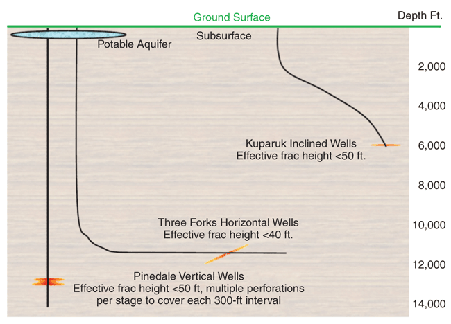
In addition to misconceptions about fracture lateral continuity and durability, there is also compelling evidence that the effective vertical fracture height is often very constrained, as illustrated by a review of the effective fracture height achieved in three very different reservoirs (Figure 1).
The Lance and Mesa Verde tight gas sandstones in the Pinedale Anticline in Wyoming are developed with vertical wells, the Bakken and Three Forks include a carbonate/shale/sandstone sequence developed with horizontal wells, and the Kuparuk formation in Alaska is a moderate-permeability sandstone developed with inclined (slant) wells.
In the Pinedale Anticline, productive gas reserves are encountered in 20-50 discrete sand intervals at 7,500-13,500 feet in depth. Wells are commonly completed with 12-25 fracturing stages that are isolated mechanically with solid bridge plugs or flow-through frac plugs. Each stimulation stage targets from one to six discrete sands, with a limited number of perforations specified to encourage injection into each perforated interval.
Fracture mapping, tracer surveys, fiber optic evaluation and production logs have indicated that some proportion of the perforations fail to take any injected fluids or produce measurable quantities of gas. Typical fracture growth above/below any specific perforation ranges from less than 10 feet to 50 feet, requiring judicious selection of perforations and a large number of stimulation treatments to complete the entire prospective interval.
The Kuparuk River Field is developed with inclined well bores from centralized gravel drill pads. The primary target of stimulation is the “A” sand (with a permeability of 20-80 mD), which is overlain by a higher-permeability “C” sand containing a mature waterflood. Aggressive fracs and refracs have been performed in hundreds of wells, often generating net pressures exceeding 1,500 psi and placing very high proppant concentrations.
Yet, water cuts have increased in only a few instances. Those few occurrences were determined to be failures of packers or inadequate near-well-bore cement sheaths, and did not indicate that hydraulic fractures grew upward through the 70-foot thick nonproductive “B” into the overlying wet C sand.
Bakken And Three Forks
The productive Middle Bakken horizon is underlain in many parts of North Dakota and Montana by the productive Three Forks, separated by a thin layer of shale (Lower Bakken). Continental Resources undertook a study to document efforts to place a conductive fracture through this thin boundary. A horizontal well was drilled in the Three Forks, hydraulically fractured in 10 stages with 958,014 pounds of proppant in 725,004 gallons of fracturing fluid and produced for 11 months prior to drilling a horizontal well in the overlying Middle Bakken. These two wells were vertically separated by the 23-foot-thick Lower Bakken.
Evaluation of the communication between these wells indicated a vertical permeability of 0.01 microDarcies. This is 4,000 times lower than the 0.04 mD sometimes quoted for horizontal permeability within the Middle Bakken. Clearly, the Lower Bakken Shale provides a natural barrier to vertical fluid movement and prohibits placing a conductive fracture from the Three Forks into the overlying Middle Bakken. This fact is why many operators have elected to drill “redundant” wells in both the Three Forks and Middle Bakken horizons. In many parts of the field, a single lateral is unable to effectively drain oil from both reservoirs, using conventional completion practices.
If the effective fracture height could be increased and durable conductive fractures placed, well count and development costs could be reduced significantly while efficiently harvesting reserves from both productive intervals. It is interesting that after depleting the pressure in the Three Forks, it was possible to fracture from the Middle Bakken downward into the Three Forks, but sustained hydraulic continuity has not been proven. In other areas of the geographically extensive play, the Lower Bakken Shale provides less of a barrier, and improved fracture designs may be capable of sustaining fracture conductivity through the shale.
In contrast, in the shallower Saskatchewan Bakken, large fracturing treatments are interpreted to grow into the immediately overlying Lodgepole, resulting in excessive brine production. In this area, smaller treatments are believed to result in reduced water cuts. Interestingly, restimulation treatments in this area frequently have been shown to reduce water cuts, and on occasion, reduce total water rates while increasing oil production.
Limited Intersection Area
A second challenge with transverse fractures is the extremely limited intersection area between the well bore and the fracture. As shown in Figure 2, a longitudinal fracture that grows along the axis of the well bore can provide a very large intersection between the well and fracture.
FIGURE 2
Well Bore Contact (Longitudinal Open-Hole,
Longitudinal Cemented and Transverse Fractures)
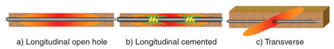
For example, a 5,000-foot open-hole lateral drilled in the direction of the maximum horizontal stress may achieve 10,000 linear feet of intersection with a longitudinal fracture. However, if a transverse fracture is created, the area of intersection is reduced drastically. For a typical six-inch diameter hole, the well bore circumference provides merely 1.6 feet of linear intersection. For both fractures to produce at the same rate, oil must travel 6,250 times faster in the transverse fracture because of converging flow geometry. When considering that pressure losses are related to velocity-squared, the near-well-bore pressure losses in the transverse fracture are increased by a factor of 6,2502, or 39 million!
In transverse fractures producing at economic flow rates, there is always incentive to increase the near-well-bore fracture conductivity, while almost any propped fracture will provide sufficient flow capacity in longitudinal fractures along open-hole well bores. If a longitudinal fracture is propagated from a cemented well bore with periodic perforation clusters, then fluid velocity can be elevated because of flow convergence, and an intermediate conductivity fracture may be appropriate.
Even when assuming simple, planar fractures and optimistic frac widths, it is evident that hydrocarbons must travel at superficial velocities 1 million times greater in a transverse fracture than in the formation, and it is challenging to place sufficient conductivity in the near-well-bore area. For this reason, operators should always be concerned with improving the width, conductivity and durability of transverse fractures near the well bore.
Liquid-Rich Formations
The elevated pressure losses in proppant packs under realistic conditions are well documented. When proppants are subjected to realistic fluid velocities, cyclic stress loading, fines migration and other conditions in an actual fracture, the effective conductivity provided by all proppant types is reduced significantly. Production of multiple fluid phases (oil, water and gas) further increases the pressure losses, often by an additional order of magnitude.
It is important to recognize that significant volumes of solution gas are liberated from oil within the fracture. At surface conditions, a gas-to-oil ratio of 550 cubic feet per barrel indicates that the produced fluids will be 99 percent gas and 1 percent liquid by volume. Few wells can be operated with a downhole pressure of one atmosphere; at higher bottom-hole flowing pressures, the gas is compressed and the volumetric ratios are reduced.
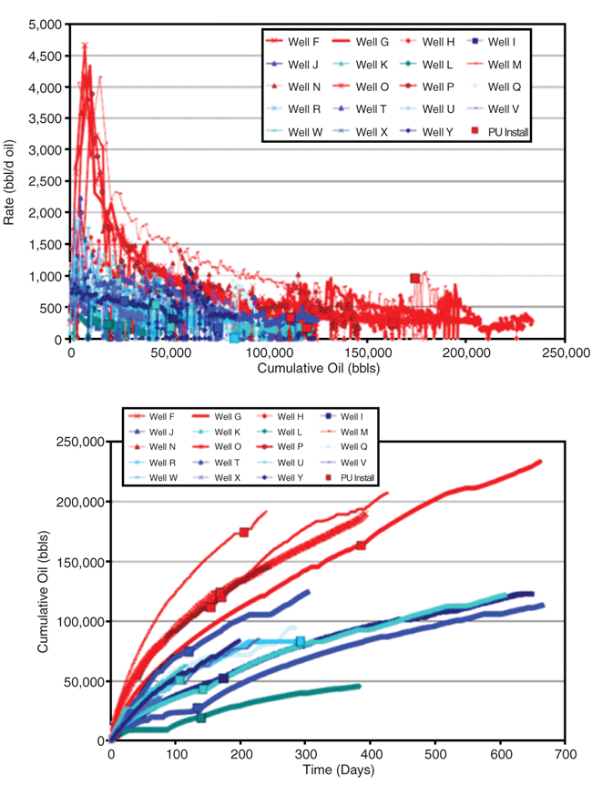
FIGURE 3A
Bakken/Three Forks Production Trends
(Red = Plug-and-Perf Stages with Ceramic Proppant;
Blue = Predominately Sliding Sleeve Stages with White Sand)
Nevertheless, significant volumes of free gas should be anticipated within propped fractures unless the bottom-hole flowing pressure of an oil well is above the bubble point. These increased volumes of gas will significantly increase the velocity of both hydrocarbon phases in the fracture, plus the interaction of fluids in a “mist flow” regime can result in further increases in the pressure losses and the corresponding need for additional conductivity within the proppant pack. A diligent frac engineer must accommodate these concerns during treatment design.
Additional concerns in developing a wet gas field involve the accumulation of less mobile liquids within the fracture below the well bore elevation. It is possible that water-submerged portions of the fracture below the well bore become essentially nonproductive in some fields. In other reservoirs, condensate banking is believed to reduce the effective formation permeability near the fracture face. Liquids also can accumulate within the well bore if significant undulations or “porpoising” of the drilled well bore trajectory creates low-lying sumps that hinder gas flow.
Some operators have attempted to drill “toe-up” laterals with minimal undulation and increase the conductivity of fractures to better remove liquids from both the well bore and fractures. Placing a pump into the heel sump can effectively remove liquids from some toe-up designs and increase well production. Using proppants with altered wettability and injecting chemicals to reduce phase trapping in the formation have had mixed success. Effective fluid removal and artificially lifting horizontal wells will remain areas of focus in developing liquid-rich formations.
In addition to the challenges of properly designing and implementing a single transverse fracture, there are operational concerns when pumping sequential stages in a horizontal well. Stage isolation practices typically involve some form of overflushing to ensure the well bore is clean. Many service companies cut proppant, wait for the slurry density to decline in the blender, and perhaps add a clean fluid “spacer” before dropping a ball to shift the stimulation sleeve.
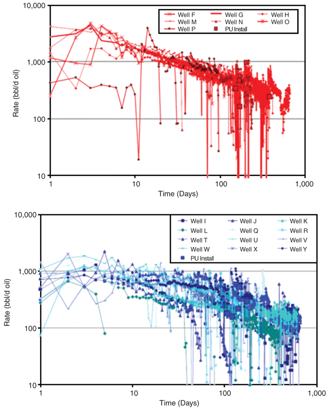
FIGURE 3B
Bakken/Three Forks Log-Log Diagnostic Plots
(Red = Ceramic Proppant; Blue = Sand)
Plug-and-perf techniques require that a plug be pumped down a relatively clean well bore, typically displacing a volume of clean fluid into previously created fractures. Many wells completed with transverse fractures are believed to have low proppant concentrations near the well bore and risk collapsing in this vulnerable region of the fracture. Production logging commonly indicates that some fraction of perforation clusters fail to produce measurable hydrocarbons. It is not yet clear whether this is caused by unseen geologic variations or is related to overflushing proppant from the near-well-bore area.
Also, because of very high hydrocarbon velocities in transverse fractures, many wells have experienced significant proppant flow back, in some cases exceeding 100,000 pounds, which may eventually result in collapsed fracture connections.
In some Bakken wells near the Canadian border, early production indicates elevated water cuts and hydrogen sulfide levels, both of which are believed to originate from the overlying Lodgepole. However, these rates decline rapidly on many wells, indicating the progressive collapse of inadequately propped portions of the fractures. While reduced H2S production is a welcome outcome, it may provide some troubling conclusions about the durability of fractures using low concentrations of low-strength proppants in this formation.
Improving Production
Several operators have attempted to improve production from transverse fractures in liquid-rich formations. In one project in the Bakken/Three Forks, efforts were made to increase the conductivity of transverse fractures using strong, thermally stable and flow-back-resistant ceramic proppants. Geosteering was used to stay in the most prospective layer of the Middle Bakken/Three Forks targets. An increased number of stages using plug-and-perf techniques was selected, and aggressive proppant concentrations, including screenouts, were implemented to improve near-well-bore connection and frac conductivity. Early production results indicate a significant increase in well productivity and an apparent increase in recoverable reserves.
FIGURE 3C
Bakken/Three Forks Diagnostic Plots (Red = Ceramic Proppant; Blue = Sand)
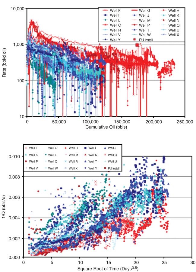
Source: Updated from Rankin, 2010
Figures 3A-3C provide performance histories of wells completed using improved completion practices (shown in red) compared with offset wells using more conventional practices of sliding sleeves and lower-conductivity frac sand (blue). The square symbols labeled “PU” indicate installation of a pumping unit. Offset wells Q, V and Y were completed with 22 frac sleeve stages plus eight plug-and-perf stages receiving white sand as proppant. Despite incorporating some plug-and-perf stages, these wells do not match the performance of the wells completed with ceramic proppants and improved completion strategies in all stages.
In another project, the refracturing of 100 Bakken wells in Montana, North Dakota and Saskatchewan were evaluated. Wells initially stimulated with sand or resin-coated sand could be profitably restimulated in up to 90 percent of the attempts. In contrast, wells initially treated with a more durable ceramic proppant appeared to benefit from restimulation in less than 50 percent of the attempts. Although a 100-well data set is not a conclusive study, this is the first field identified in which dozens of refracs were attempted on wells initially completed with sand, resin-coated sand and ceramic proppant. The field results appear to substantiate laboratory testing documenting the relative durability of proppants.
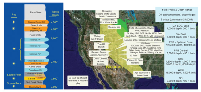
Niobrara Play
The Niobrara sequence is composed of alternating layers of chalk and shale, and was deposited from Canada to the Gulf of Mexico at depths ranging from surface outcrop to more than 24,000 feet (Figure 4). Fluid types across this area include biogenic gas, thermogenic gas and oil ranging from 32 to 62 degrees API gravity. While vertical wells have penetrated the Niobrara in thousands of locations in the Denver-Julesburg Basin, current leasing and drilling activity is focused on horizontal drilling in oil-prone regions, with more than 60 active operators.
FIGURE 4
Niobrara Strat-Section (Wattenburg Field,
Sonnenburg) and Geographical Extent
If hydraulic fractures were highly conductive features that reliably penetrated all layers of the Niobrara, equal production would be anticipated regardless of the depth of the lateral. However, well productivity in the Niobrara is highly affected by the depth at which the lateral is landed. Most operators in the heart of the Wattenberg field have reported that laterals drilled within the “B” bench have been most productive, substantiating the conclusion that hydraulic fractures completed with traditional practices fail to provide durable, conductive channels capable of draining all Niobrara layers. This has surprised some operators, since tracer data on vertical wells historically indicated that treatments could grow through the entire Niobrara interval.
Carrizo Oil & Gas has disclosed some of the drilling challenges in the play. For example, one of its early horizontal well paths encountered multiple faults ranging from five to 125 feet of displacement. Without accurate seismic or vertical well control, it was impossible to keep more than 50 percent of the drilled lateral within the desired interval, and resulting well productivity suffered. After acquiring seismic data, accurate 3-D imaging of the formation has allowed Carrizo to adjust its plans on subsequent wells to avoid faults and keep horizontal laterals within the targeted interval.
Fracture Durability
Most wells in the Niobrara have been completed with modest concentrations of sand, which often is overflushed to clear the well bore for isolating subsequent stages. While impressive initial production rates have been obtained in some areas, steep production decline curves are common and many operators are seeking ways to improve the well bore-to-fracture connection to determine whether higher production rates can be sustained with improved frac design and durability.
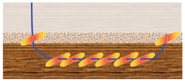
FIGURE 5
Viking Formation “U-Shaped” wells and Corresponding Completion Stages
There is growing recognition that even vertical D-J Basin wells benefit from frequent restimulation, and that restimulating Niobrara horizontal wells likely will be needed, unless steps can be taken to improve fracture durability. Experimentation with higher concentrations of durable proppants, intentional screen outs, different isolation strategies, and immediate restimulation/“hesitation fracs” is being evaluated.
As in the Niobrara, drilling activity in the Viking formation in Western Canada is targeting horizontal wells in oil-rich regions. Many operators are finding challenges in placing adequate conductivity in transverse fractures and in preventing the subsequent flow back of proppant. An additional concern is the ability to effectively drain multiple productive layers with a single horizontal well.
One novel development scenario (Figure 5) considers U-shaped wells in which both the toe and heel of the lateral are completed in the higher-permeability conglomerate, while the majority of the lateral is landed in the deeper and lower-permeability Viking, which contains the majority of the recoverable reserves. Fractures in the low-perm rock are spaced more densely than in the higher-perm conglomerate.
FIGURE 6
Eagle Ford Wells
(Red Stars = Wells with Ceramic Proppant)
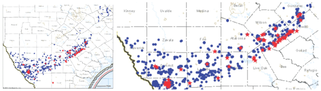
Maps courtesy of DrillingInfo.com
In the Eagle Ford, one supplier of ceramic proppant has recorded the locations of each well that has used high-conductivity ceramic proppant, denoted by the red stars in Figure 6. Unfortunately, full completion information is not publicly available, so it was not possible to immediately determine the proppant type used in the blue wells. However, the blue wells are believed to contain sand, resin-coated sand, and ceramic proppants supplied by other manufacturers, and are therefore presumed to represent lower-conductivity fractures on average as compared with the red group.
FIGURE 7
Eagle Ford Wells
(Red = Wells with Ceramic Proppant,
Blue = Unknown Proppant Type)
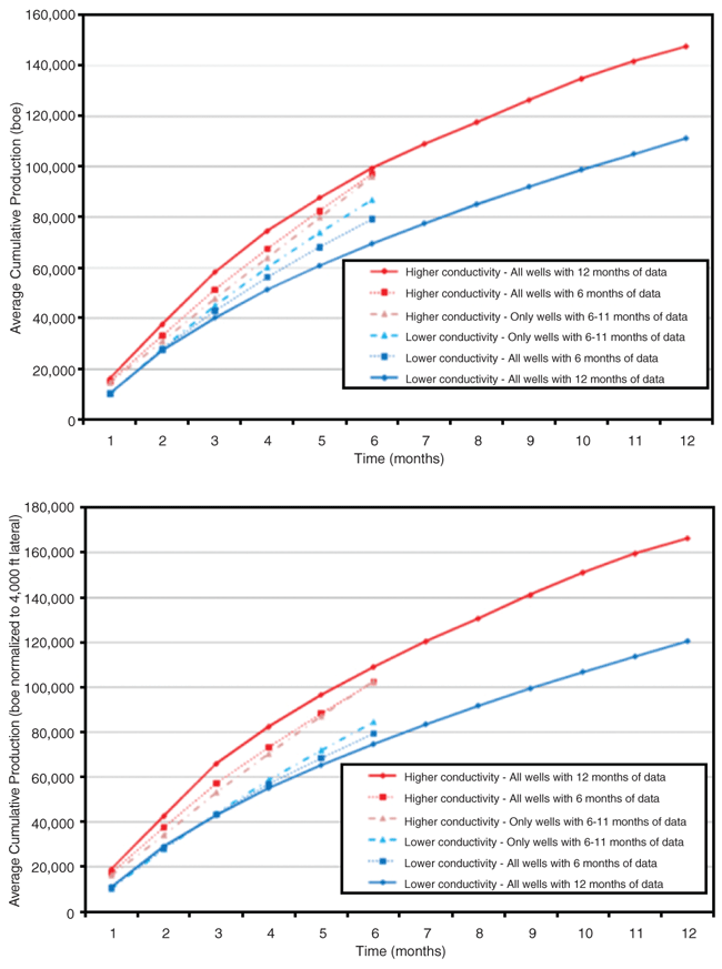
Figure 7 shows the comparison of all Eagle Ford wells with at least six months of production data available through public databases. This preliminary observational study suggests that Eagle Ford wells completed with higher-conductivity fractures provide superior production. Flowing conditions typically are not reported to public databases, so it is not possible to normalize for reservoir quality variations or flowing practices using public data. However, comparisons have been performed in smaller areas for single operators to reduce geologic variations and eliminate variables related to company completion practices, with similar conclusions. Improved frac conductivity, provided through high-quality proppant, appears to increase production from the liquid-rich formation developed with transverse fractures.
Compelling Evidence
There is increasing evidence that the depth of the lateral within the pay section influences well productivity in many unconventional formations. This finding provides compelling evidence that hydraulic fractures implemented in traditional manners do not reliably provide highly-conductive vertical channels that breach all reservoir laminations. In some cases, operators have achieved improved performance by placing high concentrations of durable proppants and making special efforts to maximize near-well-bore conductivity.
Operators also are reporting increased production in many fields with progressively closer stage spacing of transverse fracs, placing perforations more closely than typical models would suggest is optimal. In fact, operators are observing significantly higher initial rates and much higher EURs when a fixed mass of proppant is divided into increasingly greater numbers of shorter transverse fractures, rather than a few long transverse fractures. This is explained partly by substantial pressure losses in transverse fractures; increasing the number of hydrocarbon entry points reduces the “backpressure” on production.
However, it also is apparent that fractures often lose hydraulic continuity. Bakken wells that are known to be connected by a propped fracture frequently lose hydraulic communication over time. Breaking a long, discontinuous proppant pack into a number of shorter fractures appears to be a more effective use of capital investments in proppant, fluids and horsepower.
FIGURE 8
Transverse Fracture Length and Infill Drilling
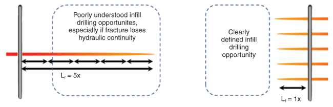
There is yet another advantage of adopting this strategy to more thoroughly drain reserves near the well bore. As depicted in Figure 8, infill drilling near horizontal wells completed with massive transverse fractures of unknown durability is fraught with uncertainty. In the Barnett, it has been reported that infill wells drilled on 385-foot spacing have recovered 80 percent of the reserves of “parent” wells drilled without adjacent competition. Clearly, initial wells are not thoroughly draining the entirety of the fractured volume indicated by microseismic mapping.
However, if the transverse fracturing treatments are broken into more entry points to more thoroughly drain the near-well-bore area, the net reserves recovered in a full development scenario may be increased significantly if a greater number of short effective fractures can replace a smaller number of longer and less efficient fractures.
Editor’s Note: The author acknowledges Brigham Exploration Company for its permission to publish updated data from the Bakken, and Mark Chapman of CARBO Ceramics for compiling data from the Eagle Ford and allowing the results to be published. For more detailed information and references, see SPE 146376, a technical paper prepared for presentation at the Society of Petroleum Engineers Annual Technical Conference & Exhibition, held Oct. 30-Nov. 2 in Denver.

MIKE VINCENT is a consulting engineer with more than 20 years of experience in economic optimization of hydraulic fractures. After completing a degree at the Colorado School of Mines, he worked with Amoco in Denver, and with ARCO in Alaska and Denver. Vincent started Insight Consulting in 1996, specializing in fracture design and reservoir analysis. He also has consulted with CARBO Ceramics since 1998, allowing him to optimize fractures in reservoirs around the world by accurately predicting production under realistic conditions. A former Society of Petroleum Engineers distinguished lecturer, Vincent has been awarded two patents, and has instructed more than 100 seminars on fluid flow, fracture design and practical production optimization. He is an SPE technical editor and serves on steering committees for several SPE meetings and workshops. Vincent also frequently lectures at universities and presents fracturing schools to numerous companies and organizations.
For other great articles about exploration, drilling, completions and production, subscribe to The American Oil & Gas Reporter and bookmark www.aogr.com.