


Growing Condensates Require Optimized Designs For Gathering, Processing
By Mark Scott and Jeff Stake
IRVING, TX.–Condensate has been coming in from gathering systems for years and has been handled in different ways. However, the industry’s focus on liquids-rich resource plays has elevated the focus on condensates and how they should be handled. Numerous factors–varying from economical to environmental drivers–have contributed to this change in priorities, but U.S. condensate production has increased in step with activity in shale plays.
Condensate is lighter than crude oil, but heavier than natural gas liquids. The issue with condensate in its natural form is that the lighter hydrocarbons can make it dangerous to store and transport. Therefore, stabilizing is required to allow the condensate to meet specifications. Often, the condensate is pumped to a sales storage tank, where it will flash off its lighter hydrocarbon components, which usually are captured through vapor recovery compression in order to prevent venting to the atmosphere, which results in lost revenues and potential emission issues.
Different operators process their condensate in different ways, based on their commercial considerations and operational preferences. Regardless, plant equipment has to be designed around a clear-cut basis, and preparations need to be made to make the project move as quickly as possible.
The U.S. Energy Information Administration describes lease condensate as “a mixture consisting primarily of hydrocarbons heavier than pentanes that is recovered as a liquid from natural gas in lease separation facilities.” This category excludes natural gas plant liquids, such as butane and propane, which are recovered at downstream processing facilities. Condensate nomenclature tends to be puzzling because different terms are sometimes used to describe the same thing, and in some instances, the same name is used to describe different compositions. An example of this is NGLs referred to as y-grade, plant condensate, natural gasoline, compression liquids, and cryogenic liquids, to name only a few.
One thing to note when referring to NGLs as natural gasoline is that there is also a product stream from an NGL fractionator that typically is composed of the pentanes and some hexanes from the fractionation process. Therefore, the term natural gasoline, when used with respect to a fractionator, will have a very specific definition. Field condensate, on the other hand, can be referred to as condensate, high API crude, oil, and drip. Most of these vary, depending on where one is located geographically and who he is talking to.
Growing Condensate Volumes
Condensate has many uses, but the primary uses are selling as a diluent in heavy crude blending, processing in a splitter into individual components, and selling as crude oil for refining. The volume of U.S. crude production that is actually condensate rose from 11 percent in 2011 to 14 percent at the end of 2012, according to the EIA. However, some industry analysts have noted that as much as 70 percent of the “crude oil” production stream in resource plays such as the Eagle Ford Shale rightly should be classified as condensate, based on API gravity specifications.
Condensate often is produced in rich gas gathering pipelines. As the gas cools from wellhead temperature to ground temperature, a percentage of the stream will “condense” as liquid. The extent of condensate production (i.e., the percentage of the gas stream that will liquefy) varies from system to system, depending on the pressure, temperature and composition of the gas. Richer gas, lower temperatures and higher pressures are all driving forces toward increased condensate production.
For a gathering system where the gas composition and operating pressure do not change significantly, the largest variable is temperature. As the ground cools during the wintertime, the pipeline and gas also will cool, causing a greater degree of condensation versus warmer summer months. Also, the composition of the condensate will change slightly throughout the year, with winter condensate containing a larger degree of lighter components.
The challenge is to accurately anticipate the quality and quantity of condensate to be produced during gathering, and to develop a design that processes the condensate to a commercially acceptable form. As mentioned, the condensate often contains lighter hydrocarbons that elevate its vapor pressure to the point that it is not saleable and is dangerous to transport. If a multistage stabilizer tower is not employed, a portion of the liquids will need to be flashed off in storage tanks, and arrangements will have to be made to capture the resulting vapors as necessary to comply with air permit requirements specific to the site.
Conceptual Process Design
When making decisions regarding a facility’s front-end liquids handling design, each case must be looked at individually in terms of the quality of gas, type of facility, transportation options, and contractual specifications. In all cases, the system should be modeled using a process simulator to predict the quality and quantity of condensate produced, and to optimize the process for each individual facility. In a rich gathering system, condensate often is encountered multiple times in various compositions as the gas makes its way from the wellhead to the processing plant.
In a typical gathering system, the first encounter with condensate is at the front end of a field compressor station. The condensate is removed as free liquid using a slug catcher, and often is at low pressure (100 psi or less, depending on the producer’s requirements). Depending on the inlet pressure, the liquids from the slug catcher can either be dumped or pumped to an atmospheric storage tank, or to an intermediate pressure bullet tank.
A vapor recovery unit (VRU) typically is employed to capture and compress the flash gas from the tank. The liquids from the tank are either pumped to the discharge pressure of the station and commingled with the gas stream for further handling and processing at the plant downstream, or sold on site as a “truckable” product.
This article looks at a plant scenario that is designed to process 130 million cubic feet a day, tracing the liquid handling process from the plant inlet slug catcher to the condensate storage tanks. In this case, the plant was constructed already, and was operating at less than the rated capacity. The plant was expecting a large volume ramp up to reach full capacity within a couple years. The gas is “sweet” (containing less than 1 percent carbon dioxide and less than 4 parts per million hydrogen sulfide), and the gas is moderately rich, with seven gallons of recoverable liquids per Mcf.
The first objective in processing the condensate is to demethanize the liquid stream to a point where it is able to be blended with the y-grade. To accomplish this, a process must be developed to reduce the capital cost as much as possible, reduce operating costs as much as possible, and maximize the amount of liquid that can be processed to y-grade, thereby minimizing the amount of condensate that flashes to vapor and increases the load to a downstream cryogenic plant. In this case, it was determined that a stabilizer is the preferred approach because it provides the best control over product spec, reduces operating cost versus compression, and maximizes the quantity of product.
FIGURE 1
Demethanized Liquids Process Flow Diagram
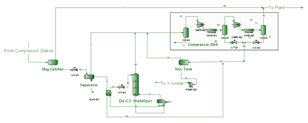
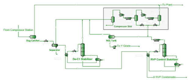
FIGURE 2
RVP Control Process Flow Diagram
In this process (Figure 1), the condensate from the slug catcher (approximately 5,000 barrels/day) will dump to a separator at a pressure of 200 psi. A portion of the vapor has flashed, leaving approximately 3,000 bbl/d of condensate remaining. The condensate is fed from the separator into a liquid/liquid exchanger, where it is warmed to 85 degrees Fahrenheit, and then enters the stabilizer tower at the top tray. The vapors from the stabilizer overhead are fed to the intermediate VRUs. The demethanized liquids are reduced to approximately 2,500 bbl/d, and then pumped to pipeline pressure to be joined with the y-grade stream.
In many cases, however, liquids pricing makes it advantageous to further process the demethanized condensate to produce a saleable condensate product. In this case, the target specification is 9.0 psi Reid vapor pressure (RVP). To accomplish this, a second stabilizer is placed in the simulation immediately downstream of the first. The demethanized liquids are sent to another liquid/liquid exchanger to be warmed to 110 degrees, and are then fed to the top tray of the RVP control stabilizer.
The vapors from the stabilizer are sent to an air cooler to be condensed. From the condenser, the stream enters the NGL tank, where vapors are captured by the intermediate VRUs and the liquids are pumped to the y-grade stream. Since the heavier components have now been removed, the liquid volume sent to y-grade is approximately 1,750 bbl/d. The liquids from the RVP control stabilizer (approximately 800 bbl/d) are now at the stable product spec of 9.0 psi RVP, and are sent to atmospheric tanks for storing prior to being trucked away (Figure 2).
A key aspect of the RVP control process is formulating a strategy for reducing engineering time and costs, identifying “critical path” items, and managing project fabrication and execution.
Project Design, Execution
Implementing an RVP control process requires assessing two areas: the construction location where the facility is to be implemented, and the fabrication process for both materials and plant fabrication. Every project has a critical path that must be evaluated upfront. The facility operator first has to decide how to handle the construction process, including deciding whether it is going to do the construction itself, or contract the equipment manufacturer or another contractor for the construction.
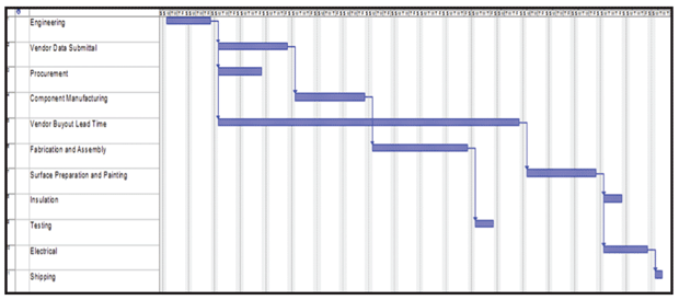
If a third party is hired for the construction, the operator has to decide how aggressive the schedule should be, including determining whether the project is valuable enough to have the contract company work overtime to expedite completion. Figure 3 shows an example schedule covering the full scope of a project from permitting to plant startup.
FIGURE 3
Example Construction Project Schedule
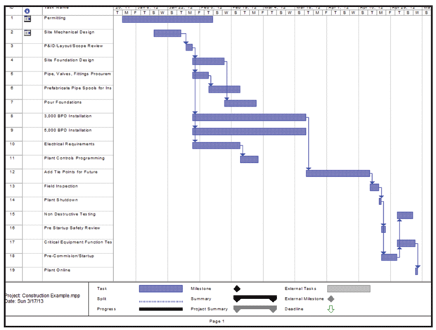
FIGURE 4
Isometric View of Stabilizer
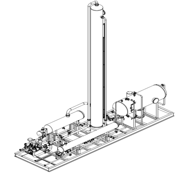
Figure 4 shows an isometric view of a stabilizer. Fabricators often have new stabilizers in stock, or a used stabilizer may be available for purchase. Either option can reduce the time it takes to complete a project. However, both also can lead to formatting the condensate around the equipment, rather than formatting the equipment around the condensate. Economics play into this decision-making process as well. There is potential for lost revenue if there is a chance the operator will not be able to stabilize all of the condensate it has access to, or has to wait a significant amount of time to bring a stabilizer on line because of grass-roots fabrication.
The project manager needs to establish a design case from which the project will be designed. Because condensate volumes fluctuate seasonally, the design case should encompass the maximum as well as the necessary turndown to handle the minimum volume. When forming the design case, it is important to establish what the condensate compositions will be throughout the year, whether sour service is expected, inlet temperatures and pressures, the desired heat medium, and whether the equipment is to be block- or skid-mounted, to name a few.
Process Simulation
In all cases, it is important to know the pros and cons. Process simulation software can greatly improve one’s ability to make knowledgeable decisions that will allow the process to be implemented in a manner most beneficial to the operating company. Evaluating all the variables is crucial to ensuring that the process is designed accordingly. Sour service could quickly deteriorate processing equipment, while temperatures and pressures need to be considered both for material selection purposes and stabilization complexity. The heat medium (hot oilers, electric heaters, steam, etc.) is also important.
Once the design case is established, the operator needs to begin working with stabilizer fabricators to find the best design to meet the project needs at the price, quality and schedule required. From a fabricator’s perspective, there are several critical pieces of equipment that play a large part in being able to complete a project on an aggressive schedule. When dealing with a condensate stabilizer, items such as the heat exchange equipment, tower shells and heads, separation equipment, filtration equipment, valves and instrumentation all can slow the process. Once all items have been sized accordingly, fabrication work can begin (Figure 5).
FIGURE 5
Example Fabrication Project
Given the demand for skilled welders, labor must be considered during the fabrication process. A shortage of available welders makes it important to ensure that the fabrication facility has the manpower necessary to complete the job on schedule. Once a fabricator has been selected to provide the required equipment, the construction process can be formatted around the equipment.
Timely delivery of drawings and equipment specifications allow the foundations and pipework to be performed prior to equipment delivery. This is where a skid-mounted design can help accelerate unit commissioning. Fabricators often provide all the interconnecting piping and wiring to accompany a skid-mounted design. This allows the construction team to have most of the work required to connect the unit when the skid-mounted unit arrives on site. Theoretically, all that is required on delivery is calibrations, connecting plant piping to the skid, and tying in electrical/instrumentation to the plant control system.
Liquids handling is becoming an increasingly important and complex part of gas processing as operators continue to encounter rich gas streams of varying compositions. Liquids processing must be planned for, and designed with careful consideration of the surrounding processes. Detailed modeling should be performed to allow operators to develop a conceptual design to provide the most effective solution possible. There are variables to consider in every project, and a plan must be put in place that includes both proper design and implementation.

MARK SCOTT is the engineering manager for Medallion Midstream LLC in Irving, Tx. He has 10 years of planning, project and process engineering experience in the midstream industry. Prior to joining Medallion earlier this year, Scott held various engineering roles at Cardinal Midstream, Devon Energy Corp., Chesapeake Midstream, and Perry Equipment Company, including system planning, designing, budgeting, process optimization, and managing capital projects. Scott has developed capital forecasts as well as engineering and managing process improvement projects. He holds a B.S. in chemical engineering from the University of Alabama.

JEFF STAKE is the technical services and business development director for Allied Equipment Inc. in Odessa, Tx. With seven years of experience in process optimization as well as project planning and execution, he oversees business development, process design engineering and project management for Allied’s process systems division. Stake previously worked in Nalco Company’s water and process services division, where he was responsible for process optimization, troubleshooting and capital development for condensate quality assurance, process reliability, and product integrity management projects. He holds a B.S. in civil engineering from Texas Tech University and an M.B.A. from the University of Phoenix.
For other great articles about exploration, drilling, completions and production, subscribe to The American Oil & Gas Reporter and bookmark www.aogr.com.

