


Multiphase Compressor Simplifies Production Facilities
By Ankush Gupta and Jeremy Pitts
HOUSTON–The top priority of any operator is capturing as much value as possible from each asset. Once an investment has been made to drill a well and build the infrastructure to produce it, the operator strives to have the well produce as much oil and gas as possible for as long as possible. Achieving that simple objective can be challenging in liquids-rich shale plays, where rapid decline rates and multiphase production flows make getting extended, sustained production more difficult.
Liquids-rich natural gas plays, in particular, present significant challenges to keeping wells flowing and maximizing production. As daily rates decline, the liquid-carrying capability of the gas decreases to the point where it becomes insufficient to keep liquids entrained in the gas stream. High-velocity flow may appear as more of a liquid “mist,” but as gas production and velocities decline, liquids begin to collect on the tubing walls, slugs start forming, liquids begin accumulating in the bottom of the well, and eventually, the liquids may stop gas production entirely.
Many strategies exist to keep liquids-rich gas wells flowing and avoid loading problems, but wellhead compression is the first tool in the life of a gas well to keep it deliquified. Compression lowers wellhead pressures and increase flowrates to eliminate liquid loading. By reducing pressures, compressors increase gas velocities and allow more hydrocarbons and water to remain in a vapor state. However, traditional compressor designs cannot tolerate high liquids content, requiring additional infrastructure and facilities to separate, store and transport the liquids.
Another compelling solution that is gaining favor in shale plays is multiphase production facilities, which eliminate the need for liquids handling infrastructure at the wellhead by moving multiphase flow downstream to a central facility for processing. However, multiphase pump systems can have low efficiencies in the high gas volume fraction (GVF) conditions typical of liquids-rich gas wells.
Multiphase compression technology is a new concept that is designed to combine the benefits of multiphase production with operating efficiencies similar to that of a traditional reciprocating compressor. The technology potentially can give producers a new option to maximize the production of multiphase wells with high gas-to-liquids ratios. It has been tested on multiple Statoil-operated wet gas wells in the Eagle Ford, successfully handling multiphase streams coming from wells without any additional separation facilities.
Avoiding Liquid Loading
A number of techniques have been used to avoid liquid load-up conditions and improve well performance, including:
- Changing tubing sizing or using smaller-diameter “velocity strings” to increase flow velocity;
- Installing wellhead compression;
- Installing plunger lift;
- Installing lift systems such as beam pumps, electric submersible pumps and progressive cavity pumps;
- Employing gas lift;
- Injecting surfactants; and
- Implementing regular swabbing.
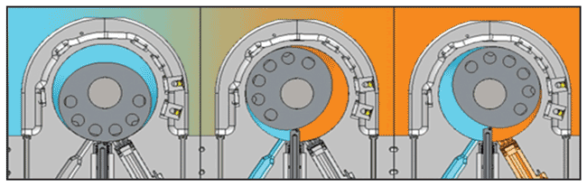
FIGURE 1
Cutaway Views of Multiphase Compression Technology
Each technique has pros and cons. Compression, for example, is not only helpful in deliquifying wells, lowering wellhead pressures, and increasing gas velocity, but deliquifying a gas well and lowering wellhead pressures can result in substantial production and reserves increases. When compression on its own is not sufficient, it can also help other types of artificial lift systems work more effectively. On the other hand, a traditional compressor requires installing a separator, heater treater, storage tanks and other facilities to remove liquids from the well stream before entering the compressor.
An alternative is moving to multiphase production facilities. Multiphase production requires only a multiphase pump/compressor and perhaps a multiphase meter on location (either at the wellhead or at a compressor station fed by multiple wells). All the other facilities can be moved to a centralized location, which achieves economies of scale and dramatically reduces compressor installation capital costs. In addition, the operating costs associated with extra liquids facilities, most notably trucking costs required to remove liquids, are eliminated. Health, safety and environmental risks also are dramatically reduced by not storing hydrocarbons on site, eliminating the risks of spills and fugitive emissions.
Multiphase compressor technology combines the benefits of both approaches. It represents a new class of rotary compressor with a stationary vane design. As shown in Figure 1, the vane moves in and out of the casing, staying in contact with a rotor and spinning inside of the chamber. The rotor is a non-circular shape, and dynamically balanced for concentric motion and minimal vibrations as the rotor spins. The rotor contains a constant radius “dwell” portion, which creates a non-contacting seal with the casing.
The left panel in Figure 1 shows the full intake volume, with suction occurring at the bottom left of the machine. As the rotor sweeps around in a clockwise direction, the dwell portion of the rotor and the vane each create a seal, allowing pressure to begin building. Once the pressure inside the chamber exceeds the downstream pressure, valves open to allow the working fluid to be discharged. The sweeping motion of the rotor and the location of the discharge allow liquids to be swept out of the compression chamber during each rotation, eliminating liquid buildup and the “hydrolocking” that is experienced with conventional reciprocating compressors.
In addition to handling multiphase flows, the liquid-tolerant design injects liquid coolant into the compression chamber. Because of the high heat capacity of liquids, this allows the compressor to achieve compression ratios of 40-to-1 or more. The extremely high ratios are attractive in liquids-rich wellhead applications because of the high flexibility they afford for suction pressures.
Process Design
A compressor package might be installed when wellhead pressure (compressor suction pressure) is 100 psig and the application requires a 400 psig discharge to flow into the gathering line. A high compression ratio and flexibility in suction pressure allow the compressor to continue operating as the well is pulled down, with the capability to pull all the way down to ambient pressure while still meeting the discharge requirements in a single stage of compression. This not only improves the economics of installing compression, since it eliminates the potential for having to swap out different compressor packages, but also may increase a well’s recoverable reserves.
FIGURE 2
Process Flow Diagram
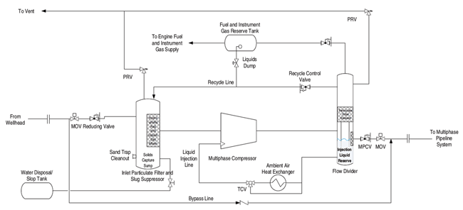
Figure 2 shows a process flow diagram of the multiphase compressor. A simple vessel is located upstream of the compressor and serves two functions: filtering out particulates from the liquid stream, and acting as a slug suppressor. Since the compressor is optimized for operation in higher GVF ranges, it cannot handle pure liquid slugs. The inlet vessel can suppress any large slugs and help regulate the fraction of liquid entering the compressor. For very large slugs, a recycle line can be used to recirculate the gas portion of the flow and work through large slugs that have built up in the inlet vessel.
A second vessel is located downstream of the compressor, and also serves two purposes. First, it separates out some of the liquids content, similar to a screw compressor package. That liquid passes through a cooler and is reinjected as coolant, enabling the high compression ratios. In an optimized system, the coolant is capable of keeping discharge temperatures low enough to avoid the need for an aftercooler. The downstream vessel’s second function is as a liquid reservoir to allow coolant to be recirculated for injection even if the well runs dry for an extended period.
Other than the two vessels, very little additional packaging is required to support a multiphase compressor. Depending on the driver being used, a fuel gas system can be integrated to make the package a completely stand-alone system, as was the case in the Eagle Ford applications. For these field trials, additional instrumentation and controls were put in place to allow for data collection and extra safety shutdowns, but a package could be constructed with minimal controls and instrumentation requirements.
Eagle Ford Applications
The Statoil-operated Eagle Ford field contains a number of wells, all feeding a central receiving plant. The central plant is equipped with compression at its intake, maintaining approximately 300 psig suction pressures. This results in various wells across the field seeing backpressures from 350 to more than 500 psig. At the time of testing, more than half the wells in the field were experiencing some level of liquid loading issues.
The field is set up for producing multiphase flows, but without any compression at the wellhead. Each well is equipped with a test separator, but no production separation or other facilities, making it ideal to drop in a multiphase compressor without requiring additional equipment. Testing was conducted in two phases. The first phase was the initial installation of the compressor to validate that it could perform as expected and produce the highly variable multiphase flows experienced in real-world conditions.
The first phase of testing was from October 2016 through March 2017. While there were challenges associated with commissioning and starting up the test (primarily associated with how to operate a compressor package in a heavy liquids environment), the testing produced favorable results. Figure 3 shows one example of test data. The skid inlet and discharge pressures are close approximations of wellhead and line pressures. In this example, the compressor came on line and pulled wellhead pressure down, stimulating liquids flow. The suction pressure flexibility of the compressor is apparent, pulling inlet pressure all the way down to 15 psig while discharge pressures still exceeded the line pressure of 350 psig.
FIGURE 3
Eagle Ford Test Well Data
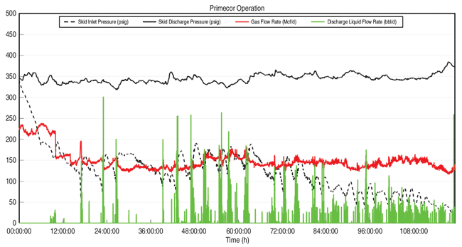
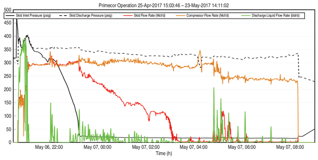
FIGURE 4
Eagle Ford Test Well Data
One challenge encountered was the compressor’s capacity and its ability to keep up with the flow of the well. This is evident in Figure 3 as the well appeared to still load up from liquids despite the compressor pulling wellhead pressure down, as the throughput at that point was only 150 Mcf a day. For much of the first phase of testing, the compressor was operated on a slip stream, allowing the well to produce at its full potential. Phase one testing concluded after verifying that the technology was able to successfully operate with greater than 90 percent availability over a long period.
A new well was selected for the second phase of testing that was expected to be a better fit for the compressor’s specifications. The goal was to prove the technology would be capable of achieving flow rates sufficient to keep a gas well from experiencing liquid loading and sustain those conditions for an extended time. This phase of testing began last May. Early testing was complicated by issues with the selected well already being heavily liquid loaded, prompting a change to a different well after only a few weeks of testing.
Figure 4 shows an example of attempting to run the compressor to unload the well. After a tumultuous startup, a large slug of liquid passed through the compressor (around 21:00). The well began flowing at that point and wellhead pressure was quickly pulled down. It became apparent that the well was still loaded, however, as it stopped producing gas shortly after its pressure was pulled down (the “skid flow rate” started to drop while the “compressor flow rate” remained high, an effect of the compressor going into an automatic recirculation mode to avoid starving the machine).
The initial evidence suggests that the technology is capable of not only keeping a well unloaded, but potentially has the ability to help unload a well, in a similar fashion to blowing a well down to an open top tank. Figure 5 shows an example. From 14:45 to 16:00, the compressor pulled wellhead pressure down to nearly zero and was in recirculation mode, essentially creating the same effect as opening a well to ambient pressure with an open top tank.
FIGURE 5
Eagle Ford Test Well Data
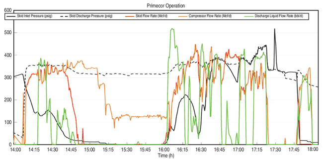
At 16:00, the well produced a large liquid slug and the compressor was able to process liquids at the rate of several hundred barrels a day over the course of the next hour or so, with the well beginning to flow again. After this unloading process, the well started producing stable flows without any additional artificial lift, which it had not been able to do in some time.
While the initial portions of the second testing phase have produced positive results, this phase has yet to achieve all of its goals. The project team is working to align the compressor’s capabilities to the output of the well to deliquify the well and provide an attractive economic return. The results of the first phase, combined with initial data from the second phase, give the team a significant amount of confidence that the test ultimately will achieve a successful outcome and demonstrate multiphase compression technology’s ability to achieve reduced line pressures without the added cost and complexity of building out wellhead liquids handling facilities.
ANKUSH GUPTA is a production engineer at Repsol, working as a secondee engineer at Statoil in the Eagle Ford joint venture asset. He has been in the Eagle Ford production group since 2013 and has been involved with production optimization of different reservoirs. Prior to production, Gupta spent five years as a drilling engineer for shale wells in Canada, Pennsylvania and Texas. He holds a mechanical engineering with management degree from McMaster University.
JEREMY PITTS is senior vice president of engineering at Hicor Technologies, where he has led the development of the company’s multiphase compression technology since its inception in 2010. He holds four U.S. and three international patents related to compression technology. Prior to Hicor, Pitts led efforts to develop and launch a variety of new products across the energy and aerospace sectors. He holds a B.S. in mechanical engineering from the California Institute of Technology, an M.S. in mechanical engineering from the Massachusetts Institute of Technology, and an M.B.A. from the MIT Sloan School of Management.
For other great articles about exploration, drilling, completions and production, subscribe to The American Oil & Gas Reporter and bookmark www.aogr.com.