


Reservoir Drill-In Fluid With Breaker System Tailored For Frio Formation
By Brittany Granger Thibodeaux, Nathan Tarver and Nathan Emery
KATY, TX.–As one of the Texas Gulf Coast’s primary oil and gas-producing formations, the Tertiary-aged Frio has been drilled extensively both on and off shore for nearly a century. However, it is a challenging operating environment, with high-inclination horizontal wells, varying formation pressures and the potential for wellbore instability in highly reactive, stressed interbedded shale/sandstone sections.
In East Texas, the Frio is known to have areas of pressure depletion and a tight window between pore and fracture pressure, requiring careful monitoring of wellbore indicators. The Marg and Anahuac Shale just above the Frio sands represent a highly reactive bentonite area that requires a fluid designed with mindful consideration of shale reactivity. This bentonitic area includes a frequent fault crossing horizontal lateral sections, introducing significant drilling and completion risks by faulting out into shale sections above the Frio.
Overcoming the challenges requires proper fluids management for better control of mud weights, filter cakes, more efficient trips and proper displacements. To drive maximum well productivity, operators are leveraging specially designed and tailored reservoir fluids to maintain wellbore stability while protecting the reservoir from drilling fluid damage.
Based on reservoir rock morphology, lithology and calculated pore size distribution, a tailored suite of fluids has been developed that demonstrate exceptional wellbore stability while minimizing the risk of formation damage in Frio applications.
The fluids are formulated with a divalent reservoir drill-in fluid (RDF) and acid precursor chemistry breaker to meet the temperature and targeted time before acid hydrolysis requirements to avoid damaging the production zone.
Using a tailored RDF and acid-precursor breaker composed of divalent and/or monovalent base brine types reduces near-wellbore damage while achieving a uniform removal of the deposited filter cake during the completion phase, ultimately leading to enhanced productivity and sustainable oil production. RDFs and breakers are designed to be safe for the environment and adhere to regulations and ESG requirements.
Tailored Fluid Design
A few key factors must be considered when designing an RDF, including minimizing skin, robust filtration and rheological profiles, readily removable filter cake, wellbore stability, and flow initiation pressure reduction. The reservoir’s chemical and mechanical properties are essential in designing the RDF and breaker fluid to ensure the integrity of the wellbore and maintaining stability.
The scope of the conceptual RDF design as established by the operator and the geological characteristics included:
- 10.6-10.8 pound/gallon RDF;
- 14-25 micron pore size;
- 200-600 milliDarcy permeability;
- 140-164 degrees Fahrenheit bottom-hole static temperature (BHST);
- Minimal (as low as possible) high-temperature, high-pressure fluid loss;
- 30-60 pounds per barrel (ppb) calcium carbonate (CaCO3);
- Shale stability; and
- Environmentally-friendly drilling fluid compared with oil-based mud.
Optimized formulation of the fluid system began with utilizing bridging software to match the particle size distribution of the RDF’s bridging agents to the pore size distribution of the reservoir. The software is based on the Ideal Packing Theory model, which can be defined as the full range of particle size distribution required to effectively seal all voids, including those created by bridging agents.
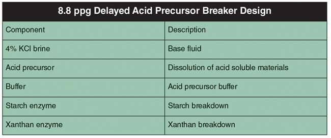
Once the conceptual design was established, lab testing was conducted using a rigorous design and selection process of divalent brine-based RDF and divalent and monovalent-based delayed acid breaker systems. This comprehensive laboratory testing led to a finalized fluid sequence tailored to the Frio formation and ready for field-trial application. Tables 1 and 2 show the final RDF and breaker fluid formulation designs.
TABLE 1
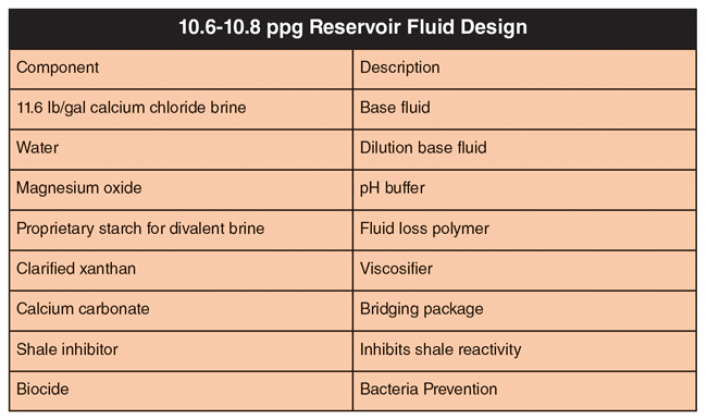
TABLE 2
Fluid preparation for the RDF consisted of utilizing a multimixer in one lab barrel aliquots with shear rates of ±11,500 rpm. All lab pilot samples were dynamically aged at a BHST of 164 degrees Fahrenheit. Fluid loss testing was also conducted (post dynamic aging) at 164 degrees with 500-psi differential pressure on a 3.0-micron aloxite disc using the 10.6 lb/gal RDF. Methylene blue testing (MBT) was conducted on two lab pilot RDF samples and a sample from the active field system for comparative analysis to measure the absorption of methylene blue by cation exchange to clay minerals in a fluid. One sample of lab pilot RDF contained no clay while the other sample contained 4% clay contamination.
A production screen test (PST) was conducted on the 10.6 lb/gal lab pilot RDF to determine any adverse plugging effects on the screens supplied by the customer: 233 x 30-mesh count reverse Dutch twill weave-type screens. The time to flow 1,000 milliliters of fluid through the screen at 10 psi was recorded four consecutive times. There was no significant lag in flow time or plugging observed during testing.
The lab pilot RDF then was contaminated with 4% clay and PST testing was repeated. Overall, the flow rates were considerably slower than the uncontaminated sample but did not fully plug off the screens. The field RDF PST results passed and was similar to both lab sample test results. The field RDF PST had to pass three times before being approved to pull out of the hole and run screens.
Breaker System
As part of the scope of the work, the breaker system was formulated to remove the RDF filter cake. Flow-through testing was conducted using the 3.0-micron aloxite disc presoaked in base fluid, and then placed into a double-ended HT/HP cell. Initial permeability rates were collected by recording the time in seconds to flow 200 milliliters of base fluid at 5 psi in the production direction, then calculating an average rate. Using the RDF, a four-hour filter cake was built on the disc using 500-psi differential pressure at 164 degrees.
The next step was to decant the residual water-based RDF, leaving the filter cake on the aloxite disc, then carefully pouring the formulated breaker along the interior sidewalls of the cell, being careful to not disturb the filter cake. The cell was heated to 164 degrees with a differential pressure of 300 psi. After observing 10 mL of breakthrough, the cell was shut in and the breaker allowed to soak for 48 hours. After the soak time, the final permeability rates were established.
After removing the disc from the cell after permeability was established, a 15% hydrochloric acid solution was dropped slowly onto the disc face to observe any potential reaction caused by remaining CaCO3. No reaction occurred, indicating that no CaCO3 remained. An iodine solution also was placed onto the disc to test for presence of residual starch, and no starch remained.
Finally, formation damage lab pilot testing was conducted using an HP/HT core flow tester and sandstone samples with similar properties to the reservoir (i.e., lithology, permeability and porosity). Testing conditions simulated the conditions of the reservoir. LVT-200 mineral oil was used to simulate production. Initial permeability was measured and recorded when stabilized. The RDF then was applied to the core to build the mud cake. During this period, the fluid leak-off was measured. The breaker was then applied and allowed to soak for a given time. When the breaker soak was concluded, the regain permeability was measured, taking care to note the lift-off pressure needed to begin flow.
FIGURE 1
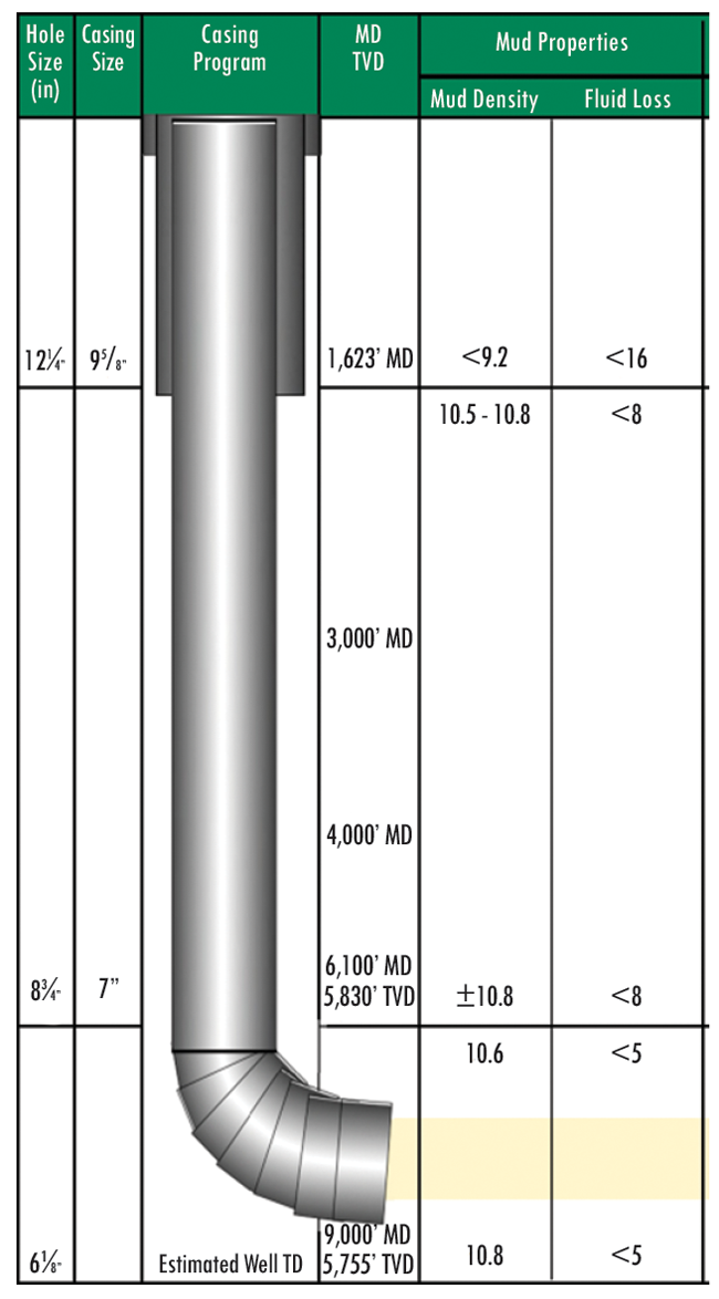
Wellbore Schematic for Well Planning
Frio Case History
Figure 1 illustrates the schematic of the wellbore in the field trial. While drilling the intermediate intervals, all RDF and breaker and sweep base fluids were built on the pad location to allow for better logistical management. The RDF was built in 200-400 barrel batches, which took four-six hours each to build.
Prior to drilling out of the intermediate casing shoe, the wellbore was displaced from freshwater to RDF with two cleaning spacers preceding. The cement, casing shoe and formation all were drilled prior to performing a successful formation integrity test. Drilling to total depth and cleaning out the well with a reamer run both were performed without issue.
FIGURE 2
Average ROP and Estimated Wellbore Porosity
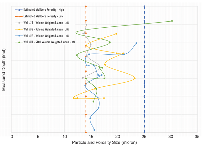
Prior to pulling out after the reamer run, three successful PSTs were performed. While drilling the well, all key properties were maintained within desired specifications. Key properties included mud weight (10.6-10.8 ppg), low gravity solids percentage (less than 8%), MBT (less than 10.0 ppbe) and average particle size distribution (14-25 microns). Figure 2 shows the average penetration rates of subject wells with estimated wellbore porosity.
These properties were controlled with whole mud dilution and screening up or down on the shakers as needed. Initial planning estimated a whole mud dilution amount of 218-364 barrels for the planned lateral lengths. Dilution rates averaged 10-12 barrels of fluid per 100 feet drilled.
FIGURE 3
Hole Cleaning Models Based on ROP and Flow Rates
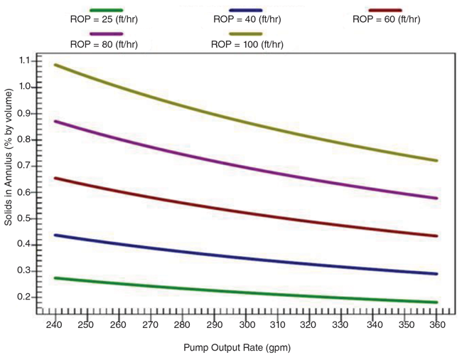
Figure 3 shows hole cleaning models based on ROP and flow rates.
The RDF and breaker fluids designed in the lab met all specifications and were deployed successfully in the field trial applications to achieve expectations. In total, 4,500 barrels of RDF fluid, 190 barrels of breaker and 300 barrels of cleaning sweeps were built on location while managing logistical and supply chain challenges to decrease trucking and improve ESG. Fluid volumes, properties, management and performance all were maintained throughout the well.
The fluid system increased productivity by significantly reducing positive skin. The completion screen assembly was run to total depth without incident and superior fluid loss control was maintained while drilling the interval. The operator was able to deliver twice as much completed lateral per well compared with a competitor in the same area of the field (2,000 versus 1,000 feet completed per lateral).
Editor’s Note: The preceding article is adapted from a paper originally prepared for presentation at the American Association of Drilling Engineers’ 2023 National Technical Conference & Exhibition, held April 4-5 in Midland.

BRITTANY GRANGER THIBODEAUX leads Newpark Resources Inc.’s technology team for Cleansorb breaker fluid and the reservoir fluids group. Brittany began her career at Halliburton in 2012, working in the cementing and drilling fluid product lines. She joined Newpark in 2019, and is involved in designing innovative technology and tailoring product chemistry and fluid solutions to maintain wellbore integrity while optimizing well productivity and injectivity. She holds a B.S. in biological sciences from Louisiana State University.

NATHAN TARVER is the technical manager for the U.S. land group in South Texas. Based at Newpark Resources Inc.’s headquarters in Katy, Tx. He began his career at Newpark in 2005 as an intern in the South Louisiana satellite laboratory. Tarver is involved in planning and oversight of projects across South and East Texas. He holds a B.S. in chemistry from the University of Louisiana at Lafayette.

NATHAN EMERY is a reservoir scientist at Newpark Resources Inc. He has more than 25 years of experience working with fluids, sand control systems and formation material. Emery joined Newpark in 2019 after serving in reservoir scientist and analyst roles at Schlumberger, Baker Hughes, PTS Laboratories and Core Laboratories. He holds a B.S in business administration from Texas Tech University.
For other great articles about exploration, drilling, completions and production, subscribe to The American Oil & Gas Reporter and bookmark www.aogr.com.