


Delaware Basin Project Deploys Advanced Diagnostics To Analyze Stimulation Design
By Nancy Zakhour, Matt Jones, Yu Zhao, Kate Orsini and Vinay Sahni
HOUSTON–A research project at the Hydraulic Fracturing Test Site-2 (HFTS-2) in the Delaware Basin tested various completion schemes. The wells were instrumented with permanent fiber optic (FO) cable, and unique near-wellbore and far-field region surveys were acquired to evaluate spatial and temporal hydraulic fracture characteristics.
State-of-the-art diagnostics included substantial monitoring of both the well stimulation and longer-term production performance. Evaluating and improving stimulation distribution effectiveness (SDE) for different completion designs based on the diagnostics results was the core objective.

A hydraulic fracturing profile (i.e., proppant/fluid allocation among clusters) was obtained using near-wellbore distributed acoustic sensing (DAS) data acquired during stimulation. Statistical analysis provided a quantitative assessment of SDE for the different completion designs.
A novel workflow assessed time-lapse fracture property changes at the cluster and stage levels based on distributed strain sensing (DSS) data acquired during the production phase. These time-lapse fracture property changes were compared with the frac profile.
Based on the statistical analysis, the results of the study indicate that rate per cluster (RPC) during proppant slurry placement appears to be a primary completion design variable, rather than the typical rate per perf (RPP). If RPC was not maintained at a certain level, the likelihood of uneven distribution increased dramatically. The stage configurations that created low RPC while maintaining high RPP did not show improved SDE.
The strain change results based on DSS data during the production phase indicated near-wellbore fracture property changes (such as aperture changes during well shut-in and flow periods) and aligned well with near-wellbore DAS signals acquired during stimulation. More importantly, fracture property changes based on DSS data acquired during two tests over a seven-month period show high consistency and good alignment with the near-wellbore frac profile.
HFTS-2 is a cost-shared, field research program located in Loving County, Tx. Occidental is the host company and operator of the program, and the 18 consortia members all acquired a rich dataset consisting of:
- Microseismic (MS) data;
- Approximately 1,500 feet of whole core (including 948 feet of stimulated rock volume core);
- Diagnostic fracture injection test data;
- Pressure-volume-temperature data;
- Quad combo and image logs;
- Proppant logs;
- Geochemical data;
- Pressure/temperature (P/T) data from 28 bottom-hole gauges; and
- Fiber optic data from one vertical pilot well and two horizontal wells.
Project Objectives
The primary objective of the HFTS-2 Completions Design of Experiments (DoE) project was to evaluate the SDE of various stimulation schemes relative to a baseline configuration. This baseline had a ~190-foot geometric stage length (SL) containing six perforation clusters (PC) with a perforation cluster spacing of 32 feet. Each PC had four perforations for a total of 24 perforations per stage, and each perforation had an average entry hole diameter of 0.41 inch. The baseline configuration was compared to more aggressive limited entry (ALE) practices achieved by reducing the number of perforations per cluster. Additionally, tapered perforations to reduce heel-side bias were tested along with extended stage length (ESL) with 10 PCs per stage at ~330 feet SL using ALE practices.
While stages treated with fewer PCs tend to have a higher SDE and better well performance, economics is the underlying issue for most operators. Although productivity may be improved by completing a well with shorter stages and fewer PCs per interval, the cost of doing so can outweigh the benefits. This dilemma begs the question of how horizontal wells in unconventional formations can be completed with longer stages and fewer intervals throughout the lateral while maintaining an effective stimulation with uniform distributions of proppant and fluid volumes, which is precisely what the study addressed.
The second objective of the study was to establish an improved understanding of stimulated rock volume (SRV) to drive enhanced field development programs by optimizing well spacing, drilling and completion configurations and strategies, and mitigating parent-child influence on performance and economics.
FIGURE 1
Map of HFTS-2 Area of Operations
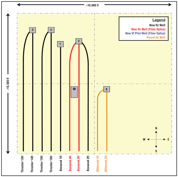
In total, there were five new horizontal wells and one new vertical pilot well that constituted the project at the time of hydraulic stimulation. Figure 1 shows the well placement. The primary horizontal wells of interest (Boxwood-1H, 2H, 3H and 4H, and Thresher-16H) were bracketed to the west by drilled, uncompleted child wells and to the east by previously completed, producing parent wells. The wells to the west (Thresher-13H, 14H, and 15H) were not considered part of the HFTS-2 project in terms of testing or diagnostics, but are shown to provide a frame of reference for the full section development plan.
Similarly, the wells to the east (Bitterroot-1H and 2H) were not considered part of the project, but are shown to indicate their proximity to the primary horizontal wells of interest, as potential depletion effects on SDE were a consideration in the project’s initial planning phases. The vertical pilot well (Boxwood-5PH) was placed between the middle and heel sections of the Boxwood-3H and 4H laterals. All of the horizontal child wells had approximately 7,500 feet of lateral length to complete, and the parent wells had approximately 4,500 feet of completed lateral length.
Diagnostics Instrumentation
To define the relationship between the primary wells of interest and illustrate the instrumentation used for data acquisition and diagnostic purposes, a simplified stratigraphic cross-section is shown in Figure 2. The horizontal wells were positioned strategically in the Wolfcamp X (WFMP_X), Wolfcamp Y (WFMP_Y), Wolfcamp A1 (WFMP_A1), and Wolfcamp A2 (WFMP_A2) target intervals with an approximate horizontal spacing of 660 feet between laterals. The Boxwood-5PH vertical pilot well traverses all the target intervals in the Wolfcamp A formation and lands within the upper portion of the Wolfcamp B (WFMP_B) formation.
Microseismic arrays were installed in Boxwood-3H, -5PH, and Thresher-16H for 3-D acoustic imaging to provide insights into fracture half-length, height, azimuth and SRV. The Boxwood-3H, 4H, and 5PH wells each were equipped with a multi-mode fiber optic cable behind casing for near-wellbore and far-field DAS and distributed temperature sensing (DTS) spatial and temporal profiling (Figure 3). Near-wellbore DAS and DTS data were acquired while stimulating the Boxwood-3H and 4H. The HF profile was obtained using DAS frequency bands extracted (FBE) data, and time-lapse fracture property changes were assessed at the PC and stage levels based on DSS data acquired during production.
FIGURE 2
Stratigraphic Cross-Section of HFTS-2
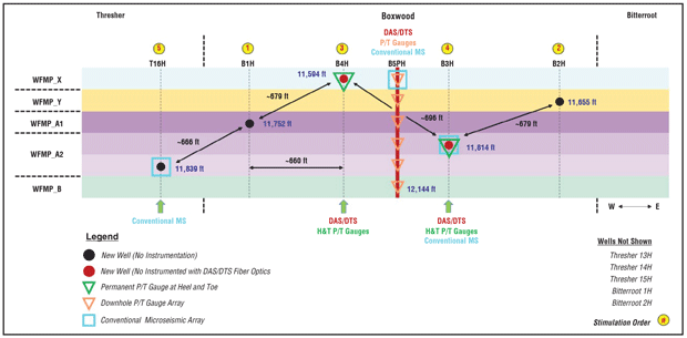
FIGURE 3
Near-Wellbore and Far-Field Surveys with FO Wells
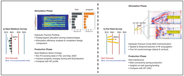
Far-field cross-well strain (FF CWS) monitoring was used for the Boxwood-1H, 2H and Thresher-16H wells as they were stimulated. FF CWS data acquired on the horizontal wells provided insights regarding minimum fracture half-lengths and azimuth, while FF CWS data acquired from the vertical pilot well provided insights regarding fracture height and azimuth.
Finally, the Boxwood-3H, 4H and 5PH wells also were equipped with downhole P/T gauges, which provided data for fracture pressure matching on the horizontal wells and fracture propagation pressures on the vertical pilot well. The P/T gauges on the horizontal wells were located at the heel and toe of the laterals. The P/T gauges on the vertical pilot well were selectively placed throughout the target intervals and isolated by packers.
Although zipper fracs typically are preferred for efficiency and reduced cycle times, the horizontal wells were stimulated through single-well operations, or “stack fracs.” Boxwood-1H was stimulated first, followed by Boxwood-2H and then Boxwood-4H. Then the MS array in Boxwood-3H was retrieved prior to its stimulation. The MS array was then retrieved from Thresher-16H, and it was subsequently completed along with the remaining Thresher-13H, 14H and 15H wells to the west. The order of operations is shown with yellow circles in Figure 2.
Not all of the horizontal wells were equipped with the same casing design configuration. Boxwood-2H, 3H and 4H were newly drilled wells that employed a 51⁄2-by-5-inch tapered production casing string, while the previously drilled Boxwood-1H and Thresher-16H were equipped with 7-by-41⁄2-inch liner designs.
Baseline Completion Configuration
With the goal of improving SDE, the project’s objectives focused on evaluating different stage configurations with varying degrees of limited entry (LE) as well as alternative perforating techniques designed to reduce the overstimulation of PCs closest to the heel. Eleven separate full-stage designs were conceptualized at the outset of the project (Figure 4). The configuration denoted as “1PC” was designed to be a single point of injection that was included in the diagnostics portion of the DoE for the purpose of DAS amplitude calibration.
FIGURE 4
Stage Configurations Conceptualized at Outset of Hydraulic Stimulation
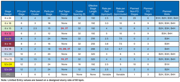
The baseline completion configuration consisted of a geometric six PC design with 32-foot spacing between PCs. This constituted a 192-foot effective stage length with four perforations per PC for a total of 24 perforations per stage, which was typically treated at 60-70 barrels a minute. Perforation entry hole diameters usually ranged from 0.38 to 0.41 inches, which resulted in a total perforation friction value of 600-1,000 psi at the end of treatment, depending on the magnitude of perforation erosion and the number of PCs still active.
While it is entirely appropriate to discuss and evaluate different stage configurations according to perforation friction, this approach can become complicated when designs with tapers are introduced, as not all PCs within the stage will have the same number of perforations. To simplify comparison between designs, the Completions DoE focused on RPP and RPC to delineate stage configurations in terms of LE aggressiveness and addressed configurations with tapered perforations in a binary manner.
The primary objective was to evaluate the SDE provided by the 6-by-24 baseline configuration and then test configurations with increasingly more aggressive LE RPP values to determine if SDE could be improved. Stages with tapered perforations also were included to eliminate, or at least reduce, the heel-side bias observed in other studies. To determine if ESLs with more PCs and relatively aggressive LE RPP values could lead to a high degree of SDE and potentially fewer stages required to complete a horizontal well, these types of configurations were included, as well.
Moreover, a slant well was planned to be drilled through the SRV for coring and fracture analysis following hydraulic stimulation and the period of initial production, so several stages with varying LE designs were strategically placed along the lateral of the Boxwood-3H.
As a controlled variable, spacing between PCs was designed to be kept constant at 32 feet on the Boxwood-3H and 4H wells for all stage configurations. Proppant and fluid volumes were also kept constant at 83,333 lb/PC and 1,833 bbl/PC, respectively. The program also tested several stage configurations with substantially more PCs and tighter PC spacing, but these could only be performed on Boxwood-1H and -2H, which did not have fiber optic cable behind casing. That necessitated perforating within casing cable protectors (CCPs) to protect the cable during stimulation. These configurations were not held to the same sand and fluid volumes per PC as described above. All proppant used was 100% 100-mesh West Texas sand.
Operational Execution
Prior to stimulating any of the new horizontal wells, fiber optic cable mapping was conducted on Boxwood-3H and 4H to determine the relative bearing (RB) of the CCPs behind the casing. This is a critical component in the stimulation process for wells equipped with fiber optic cable because the mapping results are used to prescribe perforating gun orientation angles to avoid shooting through and damaging the cable. In both Boxwood-3H and 4H, the cable makes one or more full revolutions along the length of the lateral from the toe to the heel.
While mapping the RB of the CCPs is relatively straightforward, determining which PCs should be omitted from the perforating plan is more complex. To ensure that the fiber survives the hydraulic stimulation process so DAS/DTS data can be collected during production, an overabundance of caution was used in planning the perforation process, requiring the removal of some previously planned PCs. All the perforation orientations on the Boxwood-3H and 4H were performed using eccentric weight bars and a rigorous quality control process on location prior to every plug-and-perf run. Therefore, all PCs were perforated successfully with no damage to the fiber.
The first horizontal well to be stimulated was Boxwood-1H. This well was not equipped with fiber optics for DAS/DTS data acquisition for hydraulic stimulation profiling, so the diagnostics were done with MS monitoring from the Boxwood-3H, 5PH, and Thresher-16H wells along with FF CWS monitoring on the Boxwood-3H, 4H, and 5PH wells. The 12-by-24 stage groups were strategically placed in the toe and heel sections of the lateral so any depletion effects caused by the Bitterroot-1H and 2H wells to the east could be observed and delineated. A 34th stage was planned for the well, but due to operational issues encountered on the final plug-and-perf run, that stage was omitted.
Next was the stimulation of the Boxwood-2H. As shown in Figure 1, this well was closest to the Bitterroot-1H and 2H parent wells, making it more susceptible to depletion effects than the other new horizontal wells. The stimulation objectives for Boxwood-2H were twofold. First, because the well shared the same casing design as Boxwood-3H and 4H, it was to be used as a test case for some of the more aggressive LE stage designs and oriented perforations, as well as the 1PC single-point injection, to understand how these configurations might behave from a rate and pressure perspective.
Second, as this well was offset by depletion toward the toe and by unstimulated rock toward the heel, it provided a great opportunity to collect MS and FF CWS data with different stage configurations in both settings. The stage configurations in the first half of the lateral were replicated in the second half. Stage 15, which has a 9-by-14 configuration, was meant to be a 10-by-15 configuration with ESL, tapered perforations, and an aggressive LE RPP value. Unfortunately, one of the perforating guns could not be fired during the plug-and-perf run, so a modified stage design was implemented.
DAS/DTS Well Stimulations
Next came the completion of Boxwood-4H, which was the first stimulation in the project involving DAS/DTS data acquisition for SDE assessment. The FO cable made a full 360 degree revolution from the toe to the heel. Accordingly, each stage had a prescribed perforation orientation with perforation guns set to 0 degree phasing, and all PCs were designed to be placed in the direct center of the CCPs behind casing to protect the fiber during perforating as well as during stimulation.
The progression of stage configurations through the lateral was established to evaluate the 6-by-24 base case design and then implement stages with more aggressive LE configurations to determine if an improvement in SDE could be achieved. Stages with tapered perforations also were included to determine if heel-side bias could be eliminated, or at least reduced. Configurations with ESLs were also included to determine if a relatively high degree of SDE could be maintained on stages covering more lateral footage with a higher number of PCs.
Stage 15, which was 5 by 20, was designed specifically to omit a PC for one CCP that had an orientation angle vastly different than the others in that stage. Several stages had proppant and fluid volumes less than others with the same configuration. Several stages were cut short to avoid damaging the fiber when significant acoustic energy was observed between CCPs. Ultimately, all 26 stages were perforated and stimulated with no damage to the fiber.
Boxwood-3H was the next well to be completed in this project, but first the MS array that had been installed to monitor the stimulation of the other wells had to be removed. This left one MS array in Boxwood-5PH and one in Thresher-16H during hydraulic stimulation of Boxwood-3H. FF CWS data still could be captured from the fiber optic cables on Boxwood-4H and 5PH. Like Boxwood-4H, the stimulation plan for Boxwood-3H was to evaluate the SDE of the 6-by-24 base case design followed by configurations with more aggressive LE techniques to determine if improvements could be made.
Stages with tapered perforations also were included to reduce the effects of heel-side bias, along with ESL configurations, aggressive RPP LE, and more PCs. Stages with varying configurations were placed consecutively along the lateral where the slant well later would be drilled for coring and fracture analysis purposes.
There were two misfires that occurred on Stage 1 and Stage 23 plug-and-perf runs during the hydraulic stimulation of Boxwood-3H. Stage 1 was intended to be a 6-by-24 configuration, but it was modified during operations to be a 5-by-20 configuration, similar to Stage 15 on Boxwood-4H. Stage 23 was intended to be a 10-by-20 configuration, but it was modified to be a 9-by-18.
The Boxwood-3H was significantly more difficult to treat than Boxwood-4H as a result of the large amounts of acoustic energy observed between CCPs on many stages. As a result, several stages were cut short to preserve the fiber. Regrettably, the fiber was severed during Stage 21, which eliminated the ability to read data below the damaged point, including DAS/DTS and P/T data from the gauge at the toe.
The last horizontal well to be completed was Thresher-16H. Prior to its stimulation, the MS array that previously had been installed was removed, as was the one in Boxwood-5PH. This limited its data acquisition program to only FF CWS data from Boxwood-3H and 4H, albeit in a diminished capacity as a result of the fiber damage in the Boxwood-3H during stimulation. Thresher-16H was completed with 36 stages of the 6-by-24 base case design.
There was a strong desire for the FO cables on the Boxwood-3H and 4H to survive the hydraulic stimulation so that DAS/DTS data could be acquired during production. The CCPs were designed to provide a certain level of protection to the fiber from the abrasive frac slurry, but this was only for a minimal distance on either side of the PC perforated in the middle of each protector. Any lack of cement isolation between CCPs that allowed unintended, intra-stage flow provided a substantial risk of fiber damage (Figure 5).
On both wells, but especially Boxwood-3H, several stages had to be terminated earlier than planned to mitigate this risk. These problematic stages seemed to coincide with sections along the lateral having greater degrees of relative inclination changes as well as stages between the change and the heel. This suggests that the cement isolation problem is compounding once it begins, meaning all subsequent stages are more likely to experience similar issues.
Editor’s Note: The preceding is the first of a two-part article on a completion design study at the HFTS-2. Part II appears in AOGR’s June issue and presents some of the study’s results.
This material is based on work supported by the Department of Energy under Award Number DE-FE0031577. For more detailed information on the results, see URTeC 5242, a technical paper prepared for presentation at the 2021 Unconventional Resources Technology Conference, held July 26-28 in Houston.
The authors thank Richard Sullivan, Robert Anderson, Vikram Sen and Alan Reynolds for their diligence in planning and executing this project, and thank all field personnel and vendors who ensured efficient operational execution and data acquisition of the rich dataset.
NANCY ZAKHOUR is a business development manager with Oxy Low Carbon Ventures. Previously, she was a Permian Basin well design lead at Occidental, managing drilling, completion, and production engineering design and optimization. Zakhour chaired the HFTS-2 completion engineering sub-committee. Prior to that, she was a completion engineering adviser. Before joining Occidental, Zakhour was Callon Petroleum’s completion engineering adviser and served in technical and field operational roles at Schlumberger. A recipient of the SPE Regional Completions Optimization & Technology Award, she holds a B.S. in electrical and computer engineering from the American University of Beirut and an MBA from Rice University.
MATT JONES is member of Occidental’s unconventional reservoir stimulation design team, focusing on fracture modeling and field development. From 2014 to 2019, he served at Anadarko first as a production engineer in the Eagle Ford and then as a completions engineer in the Delaware Basin. When Occidental acquired Anadarko in 2019, Jones transitioned to completions engineering supervisor for the Delaware Basin asset. He also has served as a completions engineering adviser for Occidental’s worldwide drilling & completions team. Jones holds a B.S. in petroleum engineering from Texas A&M University.
YU ZHAO is a reservoir engineer at Occidental, where he mainly conducts integrated unconventional simulation to support primary and EOR development in the Delaware and Midland basins. He also evaluates new unconventional technology for practical applications, and has extensive interests and experience in fiber optic data analysis and interpretation. Zhao is a technical reviewer for “SPE Journal,” “SPE Reservoir Evaluation & Engineering,” and “Journal of Petroleum Science & Engineering.” He holds a Ph.D. in petroleum engineering from the University of Tulsa.
KATE ORSINI is a production engineer at Oxy. Since joining the company in 2019, she has been worked in the Delaware Basin in Loving and Reeves County, Tx., focusing on production optimization, artificial lift design, and well stimulation and remediation. Orsini holds a B.S. in petroleum engineering from The University of Texas at Austin.
VINAY SAHNI works for Oxy’s Permian EOR business to develop field development plans for carbon capture, utilization and storage/carbon capture and sequestration projects. Permian EOR development responsibilities also include longer-term planning and portfolio optimization via acquisitions and trades. Sahni previously provided technical support to help optimize primary and EOR development plans for Occidental’s unconventional resources business units. Sahni holds a B.S. in petroleum engineering from Pune University and an M.S. in petroleum engineering from the University of Texas at Austin.
For other great articles about exploration, drilling, completions and production, subscribe to The American Oil & Gas Reporter and bookmark www.aogr.com.