


Embedded Sensors Speed Improvements To BHA Configurations
By D. Wayne Johnson, Steve Jones and Junichi Sugiura
During the advanced development phase of a push-the-bit rotary steerable system, downhole drilling dynamics were captured by embedding high-frequency sensors at strategic locations throughout the bottom-hole assembly. Testing took place in a challenging pocket of the Delaware Basin that had proven difficult to drill with conventional steerable motors because of rapid shoulder wear on the bit and sliding difficulties.
By providing accurate insights into drilling dynamics, embedded sensors can shed light on the factors influencing the reliability of the drill bit and BHA components, as well as overall drilling performance. Systematically analyzing this information, changing the BHA and measuring the results can drive rapid improvements to drilling speed, reliability and repeatability in specific applications.
To demonstrate how valuable understanding downhole dynamics can be, this article walks through major changes to the BHA for a 121⁄4-inch intermediate section in the Delaware Basin. In the process, it discusses several BHA configurations:
- A motor-driven RSS with a measurement-while-drilling tool placed above or below the motor;
- Similar motor-assist RSS BHAs that also include a tool for suppressing high-frequency torsional oscillations (HFTO); and
- An RSS with no motor in the BHA.
To ensure the push-the-bit RSS would be up to the job, testing needed to take place in a challenging area where the BHA likely would encounter damaging dynamics. In the onshore United States, those dynamics generally include whirl, mud motor back-drive dynamics (MMBD), HFTO, stick-slip and multiaxis shocks. Formation type, drilling parameters and rig auto-driller setup play a significant role in when these drilling dynamics initiate and how they develop.
Delaware Basin wells in the Texas counties of Ward and Loving offered an ideal proving ground. These wells’ intermediate sections pass through rock types renowned for drilling dynamics that lead to premature bit wear, rapid degradation of mud motor power sections and damage to RSS and MWD tools. Installing high-frequency sensors at multiple locations in an RSS BHA allows us to record these dynamics, compare damage to past runs and make changes to improve future runs.
The data recorders can be embedded into the drill bit, RSS, mud motor and carrier subs. The sensors are designed to capture continuous high-frequency 3-axis shocks from accelerometers and continuous forward/reverse rotation speed using a gyro. In drill bits, either they are mounted on the shank or along the center line. In mud motors, the sensors can be placed at the mud motor top sub and the bit box.
A Popular Configuration
It is common in North America land to run RSS and MWD below a mud motor. This configuration puts the MWD survey point closer to the bit, which is advantageous if there are well collision concerns. However, the disadvantage is the length of BHA below the motor. Typically, the RSS, MWD and a nonmagnetic spacing collar all hang below the motor, making motor strength and BHA stabilization critical.
With the RSS and MWD below the motor, common drilling dynamics include HFTO, MMBD and BHA/bit whirl, which can accelerate torsional fatigue on RSS and MWD electronics and mechanical components. MMBD (and the resultant stick-slip/torsional oscillations) can cause premature bit wear in certain formations, as well as speed degradation of the power section stator elastomer. BHA/bit whirl will accelerate wear and damage on some of the weaker components in the RSS, MWD and mud motor.
Figure 1 shows a typical HFTO signature while drilling through the Canyon sequence. HFTO is a type of self-excited torsional oscillation. It resembles stick-slip, but the frequencies typically exceed 50 Hz and sometimes go beyond 560 Hz. Initially, the HFTO magnitude (shown in red in the left track) was 210 Gpeak/115 Hz (tangential), but after a connection, the HFTO magnitude/frequency fell to 140 Gpeak/70 Hz (tangential).
FIGURE 1
Typical HFTO Signature With Motor-Assist RSS
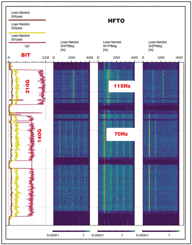
HFTO can increase fatigue to mechanical and electrical components. In this case, once HFTO was identified, an HFTO suppression tool was added to the BHA below the motor to reduce HFTO magnitude and preserve RSS/MWD reliability and life.
An important note regarding the RSS being tested is that the tool is a fully mud-operated push-the-bit system with a slow-rotating steering housing. Since the steering housing is mechanically decoupled from the rotating drive mandrel, HFTO does not pass through the slow-rotating housing that contains the control unit electronics. This design protects those sensitive electronic components from the high tangential accelerations associated with HFTO (or any high shocks present in the RSS mandrel).
The difference in g-level magnitude between the RSS lower mandrel and RSS slow-rotating housing can be remarkable. In one example, the tangential accelerations in the RSS lower mandrel reached 150 Gpeak, yet the tangential accelerations at the RSS slow-rotating housing were less than 10 Gpeak. Decoupling the RSS electronics from the mandrel’s elevated shocks significantly improves the electronics’ life and reliability.
A Destructive Combo
Figure 2 shows severe MMBD and HFTO combined. In this example, a 7/8-inch, 7.0 mud motor power section was used with 5-inch drill pipe. The second track from the left presents data from the motor top sub sensor (above power section), showing that the gyro revolutions per minute had a minimum of negative 130 (in orange) and a maximum of 350 (in blue). In the third track from the left, the mud motor bit box and RSS lower mandrel show a minimum gyro reading of zero rpm (in light green) and a maximum gyro reading of 350 rpm (in dark red).
FIGURE 2
Severe MMBD and HFTO Combined
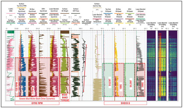
This gyro response indicates the bit is stopping, and the mud motor is driving up the drill string, causing mud motor back-drive dynamics. When the back-drive moves up the string and the torsional energy meets the rpm/torque from surface, there will be a sudden release of trapped string torsional energy, and the bit will accelerate/overspeed in the forward direction. Then the bit will stop again, and this cycle will repeat.
The bit peak tangential shock (the gray curve in the fourth track from the right) increases as the bit maximum rpm separates from the nominal (median) bit rpm. Initially, the peak tangential acceleration magnitude was around 50 g; however, toward the end of the run, the peak acceleration magnitude increased to 200 g.
The dataset indicates that MMBD amplifies the destructive nature of HFTO to the RSS and any components below the motor. The combination of MMBD and HFTO not only drastically reduces drilling efficiency, but also greatly accelerates the fatigue cycle of the motor and RSS with a motor-assist RSS BHA, decreasing the reliability of bit/BHA components.
FIGURE 3
Shoulder Cutter Wear/Damage From MMBD
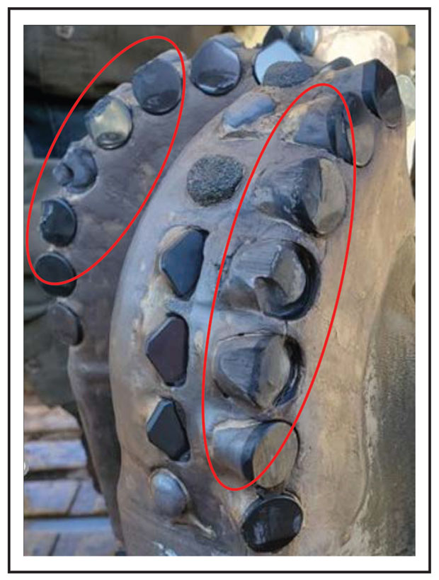
Stick-slip and torsional oscillations induced by MMBD will accelerate bit shoulder cutter wear/damage and degradation of motor power section elastomers. It is nearly impossible to eliminate MMBD when there is a mud motor in the BHA and the formation is causing the bit to stall.
When MMBD is present, the surface torque band (a spread between minimum and maximum torque values) will widen significantly. In Figure 2, the sixth track from the left shows the surface torque (in light green) spreading from 2.5 foot-pounds to 25 foot-pounds, indicating very unhealthy drilling conditions.
Figure 3 shows that the MMBD-induced stick-slip/torsional oscillations caused bit shoulder wear and lost/damaged cutting structure that led to a rapid decline in the bit’s rate of penetration. The bit damage is very similar to the damage seen with conventional steerable BHAs. If the mud motor back-drive could be eliminated from the BHA, such damage would not occur.
Auto-Driller Dysfunction
Figure 4 shows BHA and bit whirl caused by rig auto-driller dysfunction. In this example, the auto-driller weight (a brown curve in the sixth track from the left) and differential pressure (a black curve in the seventh track from the left) start chasing each other, creating the classic surface sawtooth response.
FIGURE 4
BHA and Bit Whirl From Auto-Driller Dysfunction
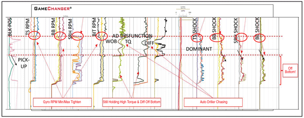
This BHA had sensors embedded in the RSS and mud motor. The data shows that when the auto-driller weight and differential pressure start chasing each other, the spread between the gyros’ minimum and maximum rpm tightens. This is true for the motor top sub (in the second track from the left), the motor bit box (in the third track from the left) and the RSS lower mandrel (in the fifth track from the left).
At the same time, the RSS slow-rotating housing (in the fourth track from the left) starts to rotate at mandrel speed. Also, the radial and tangential accelerations increase at the motor top sub (in the fourth track from the right) and motor bit box (in the third track from the right). These events all occur while on bottom drilling ahead. The sensor response indicates whirl is set up in the BHA.
When the assembly is picked up off bottom, the radial and tangential shocks at the mud motor bit box (in the third track from the right), RSS slow-rotating housing (in the second track from the right) and drill bit (in the first track from the right) increase. This change indicates that whirl has spread to the drill bit. So, while on bottom, whirl was present in the BHA but not at the bit. But once the BHA was picked up, whirl appeared in both.
The only way to remove this whirl dynamic from the assembly is to stop rotating and restart surface parameters (ideally to different auto-driller settings). The surface torque spread signature (a light green curve in the sixth track from the left) changed when the whirl was set up in the BHA. This indicates the torsional dynamic was traveling to surface at a higher frequency than the surface sensors could sample.
The damage to the MWD caused by this severe whirl can be significant. In this case, the MWD centralizer fins were ripped off. With no stabilization for the MWD assembly inside the collar, the MWD tool eventually failed from excessive lateral shocks. Running the MWD above the motor will reduce the risk of these types of damage.
The example above illustrates that BHAs with an MWD tool below the mud motor typically experience several damaging drilling dynamics. In fact, it is not uncommon to see multiple modes of dynamics ringing through the bit and BHA at the same time. Truly understanding the dynamics occurring at each point in the BHA requires data from embedded high-frequency drilling dynamics recorders.
In this example, MMBD were driving bit stick-slip and torsional oscillations that accelerated bit shoulder cutter wear/damage, leading to reduced ROP and ultimately a trip to replace the bit. At the same time, a dynamic driven by rig auto-driller dysfunction caused severe whirl at the BHA, damaging the MWD tool.
HFTO was present in the BHA below the motor. The HFTO did not cause any issues in the short term, but in the long run, it would have sped fatigue on the RSS mandrel and MWD electrical components.
Alternate Configurations
If there are no well collision concerns in the intermediate section, it is optimal to run the MWD above the motor to reduce the chance of damage to the MWD resulting from HFTO and/or whirl.
In the right formations, an MWD-above-motor BHA can still experience HFTO with a high magnitude. One well examined as part of this program had a very high HFTO magnitude of around 180 Gpeak/115 Hz. With no HFTO suppression tool in this BHA, rapid fatigue to the RSS mandrel could occur. Drilling dynamics resembling those in the MWD-below-motor configuration, such as MMBD and whirl, also can manifest.
Adding an HFTO suppression tool below the mud motor can be helpful in areas with severe HFTO. While the suppression tool will only limit magnitude (e.g. reduce the tangential g-level), that can be valuable. In a BHA with an HFTO suppressor, HFTO magnitude at the RSS lower mandrel (at the drill bit) fell from the 200 Gpeak seen in the previous example to 53 Gpeak, too low to cause rapid equipment fatigue.
Even with an HFTO suppression tool, the BHA will still encounter MMBD and whirl if the formation and drilling conditions are right. Removing the motor from the BHA can eliminate many destructive dynamics, including both MMBD and HFTO. Stick-slip and torsional dynamics still can occur, but they happen infrequently and at a much lower intensity when the string is being driven from the top drive (which means the high-frequency reactions of the mud motor and a long torsional spring below the motor are removed).
Figure 5 shows the drilling dynamics with no mud motor in the RSS BHA. The data confirms that getting rid of the motor eliminates the high-magnitude drilling dynamics driving the severe dysfunctions that caused accelerated bit shoulder cutter wear/damages.
FIGURE 5
Drilling Dynamics With Motorless RSS BHA
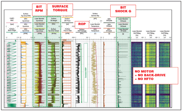
HFTO and back-drive no longer occur. The shocks at the bit (in the fourth track from the right) are low, the gyro spread at the bit (in the third track from the left) is low, and the surface torque signature (in the fourth track from the left) is healthy. This run drilled through all the 3rd Bone Spring sequence and into the Wolfcamp, and the bit came out green.
The motorless BHA delivered performance and cost advantages. Removal of the mud motor and HFTO suppression tool reduces the BHA operating, service and lost-in-hole costs. The bits can come out in a better condition and can be re-run, shrinking bit costs. The number of bit trips also falls, and with no MMBD in the BHA, ROP remains constant and predictable throughout the run. Assuming the top drive and drill pipe are adequate for the job, there are multiple positive aspects to drilling vertical or low-angle intermediate sections with no mud motor in the BHA.
Going motorless may not always be possible, but gathering downhole data with embedded sensors can unlock incremental improvements to the BHA that improve performance and operating costs. In this case, a motor-assist RSS BHA with the RSS and MWD below the motor suffered from both MMBD and HFTO. Elevated HFTO magnitudes (tangential acceleration of 200 Gpeak) were observed. Examining the downhole data revealed MMBD caused the bit to experience full-stall stick slip, elevating the peak HFTO magnitude at the bit.
Placing the MWD above the mud motor can enhance equipment survivability, though high HFTO magnitudes (tangential acceleration of 180 Gpeak) may persist. However, an MWD tool must stay below the motor if well collision risks are present during the nudge section of the well. HFTO suppression tools can help protect equipment and should be used when the HFTO magnitude is high enough to justify the additional cost. In our example, the HFTO suppressor reduced tangential acceleration from 200 Gpeak to 53 Gpeak.
Switching to a BHA with no motor can deliver significant cost and performance gains. In this test, the motorless BHA eliminated MMBD and HFTO, enabling it to drill through the 3rd Bone Spring sequence and into the Wolfcamp with consistent ROP. Eliminating MMBD and HFTO from the assembly, as well as the cost for the mud motor and HFTO suppression tool, is a financial game changer if it empowers the RSS assemblies to deliver good ROP with fewer bit trips.
Editor’s Note: This article is adapted from “Rotary Steerable Drilling Dynamics and Associated BHA Changes to Improve Overall BHA Performance and Reliability,” a paper originally presented at the Society of Petroleum Engineers/International Association of Drilling Contractors International Drilling Conference and Exhibition, which was held March 6-9 in Stavanger, Norway. The authors thank Devon Energy and Sanvean Technologies LLC for permitting this work to be published.

D. WAYNE JOHNSON is a senior production engineer at Devon Energy and previously has served Devon as a senior drilling engineer. Before joining the company, Johnson worked as a senior reservoir engineer and a drilling engineer at Newfield Exploration, where he supported exploration and development work in the Arkoma, SCOOP/STACK, Granite Wash and Marcellus plays. He holds a B.S. in petroleum engineering with a minor in geology from the University of Oklahoma.

STEVE JONES is the president and chief executive officer of Sanvean Technologies, which provides downhole measurement and control systems for directional drilling. He has 28 years of experience in directional drilling, rotary steerable systems, research and development, and product management, including domestic and international work for Halliburton, Pathfinder Energy Services and Schlumberger. Jones has published more than 35 technical papers on drilling technology and has more than 28 patents and pending patents worldwide.

JUNICHI SUGIURA is the vice president and co-founder of Sanvean Technologies. He was formerly a Schlumberger principal engineer in the United Kingdom. In addition to authoring more than 70 external publications or presentations and holding 60 U.S. patents or pending patents related to downhole technology, Sugiura has a long history of participating in industry associations. From 2012 to 2023, he served as a session chair and as Drilling/Completions Program Committee chair for the Society of Petroleum Engineers/International Association of Drilling Contractors International Drilling Conference and the SPE Annual Technical Conference and Exhibition. He also is an executive editor for “Geoenergy Science and Engineering,” an associate editor for “SPE Drilling & Completion,” and a technical editor for “SPE Journal.”
For other great articles about exploration, drilling, completions and production, subscribe to The American Oil & Gas Reporter and bookmark www.aogr.com.