Engineered Microparticles Improve Formation Breakdown, Optimize Well Productivity
By Amr Radwan
BERWYN, PA.–The overall goal of a stimulation treatment is to achieve the designed treatment profiles, including the pumping rate and treatment pressure. However, insufficient formation breakdown and presence of near-wellbore tortuosity make it challenging to reach the designed pumping rate and lead to premature screen-outs. Screen-outs during a fracturing operation diminish the well’s total production and add cost to conduct a wellbore cleanout. In some cases, these issues could cause suboptimal perforation cluster efficiency and production losses.
There is a critical need for an easy-to-implement solution that can help operators achieve their desired fracture designs. Fortunately, field applications are demonstrating the benefits of a new microparticles-based slurry (MPS) technology in improving production in multiple U.S. shale basins by reducing near-wellbore tortuosity and improving formation breakdown. To date, MPS has been pumped in more than 27,000 stimulation stages in the:
- Wolfcamp, Bone Spring and San Andres formations in the Permian Basin;
- Niobrara and Codell formations in the Denver-Julesburg Basin;
- Woodford and Meramec formations in the SCOOP/STACK play; and
- Mowry and other tight formations in the Powder River Basin.
The nonhazardous water-based slurry contains engineered glass microparticles with a median size of 550-625 mesh. Compatible with common fracturing fluids, it usually is brought on site in fluid tankers and deployed as an additive to the pad or as a pill before pumping the proppant-laden slurries. MPS technology helps in scouring the perforations and lessening fracture entry restrictions, resulting in better fracture initiation and reduced screen-out potential. It also widens fracture openings, restricts fracture complexity, reduces near-wellbore tortuosity and increases reservoir connectivity. The slurry also can be used as a far-field diverter pill.
Field studies in multiple challenging formations involving alternating stages between the microparticle slurry and the standard control show a 12%-25% reduction in pump time thanks to significant pressure relief. On another pad, MPS reduced screen-outs by more than sixfold. Production data shows up to a 19% uplift within a 15-month period against control wells. The production improvement analysis is the subject of further study, but oil and water tracer tests have confirmed the production improvement in stages using microparticle slurry.
Realizing a treatment design is a critical step in maximizing the rate of return on a well, MPS offers operators a simple, cost-effective and field-proven solution to alleviate operational issues, and potentially, design more aggressive completions. The diverse case studies prove the efficacy of this innovative technology in solving the major day-to-day fracturing challenges faced by completion engineers.
Stimulation Challenges
Each stimulated perforation results in a complex fracture network consisting of both micro- and natural fractures. Well productivity is dependent on the induced fracture aperture and width, and the ability of proppants to keep the fractures open. Proppant size can dictate long-term productivity through the micro-fracture and natural fracture networks.
Pressure pumping usually begins at a slow rate as wellhead pressure starts to build and then increases to a level sufficient to break down the formation. There often is a lack of control on the distribution of fluid volume and proppant mass into each perforation because of the differences in each perforation location. Fluid and proppants can be injected into some perforations to a larger extent, and this results in uneven fractures and understimulated formation. Perforations close to the horizontal heel typically are more stimulated than the lateral toe.
Another factor is near-wellbore pressure loss, which yields poor proppant placement. The pumping rate has a direct relationship to the perforation friction pressure, adding to near-wellbore pressure loss. A step-down test that records pressure while the injection rate is decreased step by step rather than instantaneously is used to identify near-wellbore pressure loss. A plot of bottomhole treatment pressures as a function of pumping rate can indicate the dominance of near-wellbore pressure loss.
Pressure-dependent fluid leak off can also determine stimulation effectiveness. Fluid leak off into the matrix or natural fractures may be detected by a slow increase in pumping rates (rather than fast and steady) with the possibility of never attaining the designed rate. The rate of fluid leak-off is believed to be higher through the fracture tip.
High fluid leak off is unlikely to initiate fractures because the leaked fluids would dry the proppant, eventually causing clumping near the perforations. The increase in friction pressure also can restrict proppants’ ability to enter these perforations, eventually resulting in a screen-out. Proppant screen- out significantly delays the stimulation process and is expensive to resolve. Even if a screen-out does not happen, completion engineers face a difficult challenge of obtaining their designed pumping rates and pressures because of these issues.
The combination of near-wellbore pressure loss and pressure dependent leak off can create tortuous flow paths connecting the wellbore to the main body of the fracture. The formation of tortuous fractures is related to several complicated factors, including near-wellbore stresses and hydraulic conductivity of the pathways. Any pathway where fluid can penetrate more readily will have a higher probability to be initiated and grown. These paths make it difficult for proppants to flow into the fracture, and eventually cause clumps in the wellbore. Tortuous paths also negatively affect stimulated reservoir volume and are undesirable for long-term production.
Numerous strategies with varying degrees of success have been attempted to reduce the effects of near-wellbore pressure loss, pressure-dependent leak offs and near-wellbore tortuosity, including viscous gels, friction reducing agents, proppant slugs and far-field divertors. MPS technology gives operators a new solution for overcoming these challenges, particularly in challenging formations where the screen-out potential is high.
MPS Technology
The aqueous slurry consists of 1–100-micron glass-quality silica. The small size allows it to access and prop microfracture networks where even traditional 200-mesh proppants cannot. The slurry is used in its liquid form and does not present any health, safety or environmental issues. MPS technology offers several operational benefits, including:
- Lower breakdown pressure and near-wellbore tortuosity;
- Reduced pump time and treatment pressure;
- Decreased screen-out probability;
- Far-field micro-diversion; and
- Minimal fracture entry restrictions.
Field applications show the production benefits, including a decrease in decline rates attributed to expanding the stimulated reservoir volume (SRV), propping induced micro and natural fracture networks and achieving longer and more dominant fractures.
Production enhancement with MPS has been confirmed by tracer tests in a well drilled into the Permian Basin San Andres formation, where the technology was applied to complete 23 of 38 stages. To increase the reproducibility of obtained tracer data, the control and MPS stages were distributed evenly in an MPS-MPS-control sequence along the lateral, except the tip and toe intervals. Figure 1 shows the comparison of an average concentration of tracer in parts per million (ppm) in oil and water phase produced from the control and MPS stages. Both oil and water tracer data indicated that application of MPS enhanced production.
In the D-J Basin, MPS was used on one of two zipper pads consisting of a total of 11 wells. All wells on both zipper pads had 56 stages. The design of these wells included 900 pounds of proppant per foot and 2,750 barrels of fluid per stage. Zipper A consisted of five wells (Nos. 1-5) completed without MPS. Zipper B consisted of six wells (Nos. 6-10) completed with MPS in every other stage. Every stage of well No. 11 was completed with MPS as a far-field divertor pill before pumping the proppant.
Figure 2 presents a summary of the treatment times and pressures from the two zipper pads. On average, Zipper B had 5% (~317 psi) and 12% (~6.7 minutes) reductions in the treatment pressure and pumping times, respectively, using MPS. Moreover, Figure 3 shows that the failure rate (screen-outs) was reduced from 2.9% to 0.7% with MPS. Zipper A without MPS lost eight of the 280 total stages, while the non-MPS stages of Zipper B only lost three of 154 total stages. Only one of the 151 stages with MPS screened out.
Well No. 10 in Pad B demonstrated the best example of the effectiveness of MPS to eliminate screen-outs. Stages 28 and 30 were completed without MPS (both failed), while stages 27, 29 and 31 were completed with MPS (all three were successful).
Results showed that treatment rates were higher when MPS was used in the pad, thereby decreasing pumping times. The treating pressure and breakdown pressure were also lower with MPS compared with the treating pressure without MPS. Slurry rates also were achieved quicker when MPS was pumped with the pad compared with the ones without MPS.
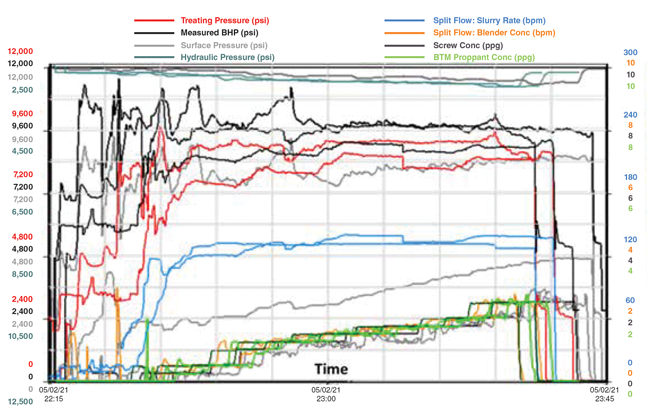
Well No. 6 on Pad B was completed in a difficult area where screen-outs were known to be prevalent. Figure 4 presents the treatment pressure plot for stages 14-17. The colored lines represent stages completed with MPS. Stage 16 (no MPS) screened out. The pumping rates were low and rate ramp up was gradual. Stages 15 and 17 were completed using MPS and did not face screen-out issues. The pumping rates were achieved quickly, and treatment pressures were reduced.
The field applications of MPS underscore the technology’s potential to help operators maximize the stimulated reservoir volume and long-term productivity of every completion in shale plays by minimizing near-wellbore tortuosity and excessive fluid losses, the primary reasons for screen-outs.
MPS is easy to apply and does not add complexity to field operations. Yet, field results show the technology reduces pumping times and treatment pressures compared with offset wells, allowing design pumping rates to be achieved more quickly. Compared with stages where MPS was not implemented, it also shows the ability to reduce screen-outs, especially in the most challenging environments.
Editor’s Note: For additional case histories on MPS technology, see SPE 210364. The preceding article is adapted from this technical paper, which was originally prepared for presentation at the Society of Petroleum Engineers’ 2022 Annual Technical Conference & Exhibition, held October 3-5 in Houston.

AMR RADWAN is co-founder and chief technology officer of TenEx Technologies. Before starting TenEx, he managed North American technical sales and business development for Sahara Petroleum Services and served as vice president of technology and innovation at Preferred Sands. Earlier in his career, Radwan held engineering roles related to drilling, completion, production and workover operations. He holds a B.S. and an M.S. in petroleum engineering from Cairo University.
For other great articles about exploration, drilling, completions and production, subscribe to The American Oil & Gas Reporter and bookmark www.aogr.com.


