


HFTS Yielding Key Fracturing Insights
By Jordan Ciezobka, James Courtier and Joe Wicker
DES PLAINES, IL.–The Hydraulic Fracture Test Site (HFTS) is a field-based hydraulic fracturing research experiment in the eastern part of the Midland Basin between the Central Basin Platform and Eastern Shelf. The $25 million research program fosters collaboration between experts from the industry, academia and government in addressing fundamental questions about hydraulic fracturing behavior within an unconventional resource development setting.
The principal objectives of HFTS include researching methods to reduce and minimize potential environmental impacts, demonstrate safe reliable operations and to improve the hydraulic fracturing efficiency of horizontal shale wells. The study has pumped more than 400 frac stages in 11 long-lateral horizontal wells drilled in the Upper (six wells) and Middle Wolfcamp (five wells) formations (Figure 1), as well as two recompleted legacy wells.
FIGURE 1
HFTS Location in Midland Basin and Site Layout
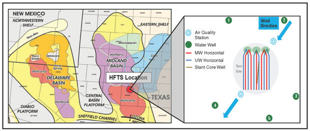
In addition to collecting comprehensive field data, approximately 600 feet of excellent-quality, whole core has been obtained by drilling a high-angle slant core well (SCW) directly through induced hydraulic fractures post-completion at a central location within the test site. Considered an industry first in the Permian Basin, the SCW (shown as a yellow-black dotted line at right in Figure 1) was drilled at an 82-degree inclination between two adjacent producing wells within a development spacing configuration in the Upper and Middle Wolfcamp formations.
Based on observations of the acquired core, the understanding of hydraulic fracture propagation and effectiveness of proppant placement is challenging current thinking. Well interference testing and in situ reservoir pressure measurements using bottom-hole gauges in producing wells and discrete multilevel pressure gauges in an offset monitor well aid in understating fracture connectivity and conductivity over time.
The HFTS is located in Reagan County, Tx., in an area covered by a high-quality 3-D seismic survey and surrounded by many producing horizontal and vertical wells. Several adjacent wells contain open- and cased-hole petrophysical, production and image logs, as well as whole cores and sidewall cores. In addition, microseismic and tiltmeter surveys were collected during the stimulation of all wells.
The 11 horizontal wells all have extended lateral sections of more than 10,000 feet, drilled from north to south, and approximately normal to the predicted maximum horizontal stress orientation. In total, more than 400 hydraulic fracture stages were pumped in the test wells, of which the majority were traced and/or monitored with advanced diagnostics.
Comprehensive acquired data include microdiagnostic formation injection tests, advanced open-hole logs, 110 sidewall cores, complete (whole) core analysis, petrophysical evaluation, geomechanical analysis, petrographic imaging, tracer analysis, microseismic mapping, tiltmeter surveys, bottom-hole pressure data, and multiple pre- and post-treatment cross-well seismic surveys. In addition, air and water samples were collected before, during and after fracturing to monitor and assess potential environmental impacts from the fracturing operations.
At the HFTS, industry partners provide access to new and existing producing wells, science wells, and background data such as 3-D seismic, geomechanical and petrophysical data. Using existing producing wells for diagnostic instrumentation and observations in proximity to test wells brings significant cost savings, while linking the research and results with actual production. In addition, industry participation provides early buy-in to the program and its results, leading to early adoption of advanced technologies and results, which is the most effective technology transfer mechanism.
Slant Core Well
The SCW was designed to collect whole core through the stimulated reservoir volume both above and below the adjacent producing wells from which the hydraulic fractures originate. About 450 feet of continuous core was recovered in the Upper Wolfcamp, representing 60 vertical feet of the fractured reservoir at 89 horizontal feet from the nearest completion stage. An additional 150 feet of core were recovered in the Middle Wolfcamp at 135 horizontal feet from the nearest completion stage. It showed considerably less fracturing than the Upper Wolfcamp portion.
Once at surface, gamma ray logging was conducted to identify the presence of radioactive tracers pumped during the completion of the horizontal wells. Radioactive tracers were not detected during core logging or in drill cuttings sampling. Cut ends of the three-foot core sections were photographed to document their states prior to laboratory transport.
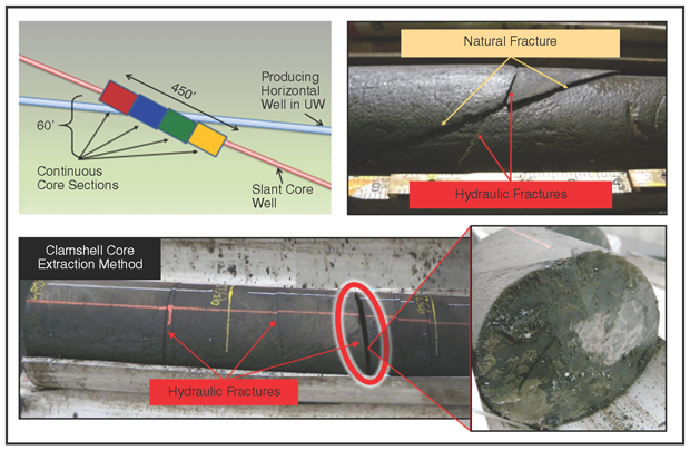
The SCW trajectory enabled the collection of core with varying lateral distance from adjacent producing wells to provide insights into both the vertical and horizontal fracture geometries. Figure 2 (upper left) shows an example of the SCW trajectory with respect to the offset producing horizontals. During drilling operations, cuttings samples were collected every five feet to obtain additional proppant and lithology information along the path of the cored interval. Mass spectrometry data were analyzed with the intent of assessing reservoir compartmentalization and hydraulic fracture identification, but did not yield any fundamental insights.
FIGURE 2
Wolfcamp Core Interval and Hydraulic/Natural Fractures
Once coring was completed, the curve and lateral sections of the SCW were logged utilizing a quad-combo logging suite, including an image log (oil-based mud imager). The log data and additional information collected while drilling, specifically the image log, were used to supplement the core data and aid fracture analysis in lateral sections where core was not obtained. After logging, the well was cased and cemented, and multiple isolated gauges were installed to monitor pressures at select intervals within the producing wells and target formations. These gauges, along with additional pressure gauges placed in producing horizontals and select offset legacy wells, were monitored for pressure changes during production.
CT scans before removing core from the barrels assisted in determining core integrity as well as the best extraction methodology, since maintaining core in a pristine condition was critical for physical fracture description. Figure 2 (bottom) shows a whole core interval after using the “clamshell” core barrel extraction method, with a hydraulic fracture in the right panel. CT scans were also utilized to differentiate in situ (natural and hydraulic) fractures from fractures created while removing core from the barrels.
The recovered core captured hundreds of hydraulic and natural fractures, and in many cases, captured the interaction of a hydraulic fracture with a natural fracture. Comprehensive hydraulic and natural fracture characterization was performed. Figure 2 (upper right) shows a hydraulic fracture cutting across a natural fracture with a slight offset. Documented SCW hydraulic fracture frequency and complexity is considered to greatly exceed current industry technology with respect to hydraulic fracture modeling and simulation technology. Results from the SCW, subsurface proppant distribution, and insights from other acquired datasets are providing the basis for the research team to visualize and describe the physical parameters of the subsurface hydraulic fracturing process.
Proppant Analysis
The recovered core provides a unique opportunity to not only capture hydraulic and natural fractures, but also to capture material contained within the fractures. It was anticipated that proppant would be discovered in the collected whole core within hydraulic fractures. Following core extraction, sludge residue was recovered from coring operations within the core barrels, including drilling mud, rock cuttings, proppant and aluminum shavings generated during cutting the barrels to remove core. A sample was collected and catalogued by depth interval for each three-foot cut core section. Most of the sludge was located on the exterior of the core, and within the core barrel.
Determining proppant distribution within the stimulated reservoir volume was a primary objective, so ensuring accurate and reliable proppant detection protocols within the SCW interval was of paramount importance. Detailed sampling procedures of proppant and associated residues were undertaken on all fracture faces, the exterior core surface, and within core sleeves. Samples were processed following cleaning and preparation, and the dried, segmented and weighed samples then were scanned using high-resolution transparency imaging. Imaged samples were processed using an automated image processing workflow to detect all identifiable particles of interest, including proppant, natural calcite and shale.
Lateral and vertical proppant distribution has been documented via proprietary workflows developed by the HFTS consortia, which when incorporated with other available data, is anticipated to improve proppant distribution modeling and simulation technologies. To identify the origin of hydraulic fractures and proppant located within the SCW, more than 20 unique chemical oil and water tracers were pumped during completion operations, as well as colored proppant. To detect the radioactive oil and water tracers, an extensive fluid sampling and well logging program was employed in newly drilled producing wells and some pre-existing offsets.
Water And Air Quality
Water for hydraulic fracturing operations was supplied from local water wells as well as treated produced water. Water quality monitoring of five landowner-owned water wells within 5,000 feet of the HFTS provides insights into any potential impact of unconventional oil and gas operations. There is no detectable communication between the shallow Edward-Trinity Plateau reservoir and deeper hydrocarbon-bearing zones activated by stimulation and production efforts. Levels of methane and BTEX have remained at “nondetectable” levels, and there was no increase in constituents related to hydraulic fracture fluids from February 2015 through January 2017.
While supplying water for hydraulic fracturing operations, increases in total dissolved solids (TDS) and conductivity were detected in the water wells. There were no changes in total organic carbon or other oil and gas indicators. These anomalies are attributed to the drawdown of the local water supply for hydraulic fracturing and the subsequent influx of water to the water reservoir from more saline regions. This portion of the aquifer has been identified as a “priority groundwater management area” by the Texas Water Development Board, and is less likely to quickly assimilate large changes in volumes. TDS and conductivity levels remained within normal ranges for the aquifer. When sampled six weeks after initial production, water quality had returned to base line.
Microseismic and tiltmeter survey data further indicate hydraulic fractures do not grow into freshwater zones.
Likewise, air quality data gathered at HFTS indicate that hydraulic fracturing and production of the 11 test wells do not affect local air quality. Methane, particulate matter, volatile organic compounds, and nitrogen oxide were measured both 1,000 feet upwind and 1,000 feet downwind from the HFTS site, and air quality data were acquired before stimulation to serve as a base line. The same air sampling techniques were used to measure air quality at the closest city (downtown Midland) to provide an urban reference point. Hydraulic fracturing and production operations did not alter air quality 1,000 feet from the well pad. Air quality on site was similar to Midland.
VRF Method
Most hydraulic fracturing designs in shale wells use a predetermined fluid pump rate, which once achieved is held constant throughout the treatment, excluding situations when surface pressure limitations or other conditions prohibit it. The HFTS has undergone successful testing of a new patented variable rate fracturing (VRF) method by which the fluid pump rate is rapidly changed from a predetermined maximum rate, to some significantly lower rate, and then rapidly increased back to the original maximum rate.
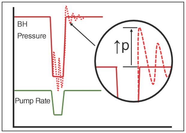
The rapid changes in the fluid flow rate temporarily produce a pressure pulse (p) of hundreds to thousands of psi (Figure 3). This pulse propagates in the wellbore from the surface to the perforations. If the created pulse pressure combined with bottom-hole pressure is higher than perforation breakdown pressure, previously unopened perforations will open and initiate new fractures. Real-time analysis of both the perforation efficiency as well as the downhole pressure response allowed for careful design and implementation of these rate fluctuations.
FIGURE 3
Rate Pulse and Resulting Pressure Pulse from Variable Rate Fracturing
In the test well, the rate pulses were executed throughout each fracture stage, including the pad and slurry portions of each stage. Rate pulses are critical to increasing the number of open perforations, which in turn, creates additional hydraulic fractures immediately near the well and extending into the reservoir to improve the connection to the shale reservoir matrix. Newly drilled and completed offset wells were used to base line the VRF test well. Production was compared with the offset wells that did not include VRF but had similar completion designs with the same or higher proppant loading. The VRF test well clearly outperformed four adjacent wells in both initial production rate and cumulative production, even after 24 months.
Fracture Diagnostics
The oil-based, water-based and radioactive tracers were pumped during completion operations to measure communication during the initial production period. Fluid samples were analyzed periodically through the first two years of production and showed limited hydraulic communication between the Upper and Middle Wolfcamp producing reservoirs, with the amount of communication decreasing over time.
The hydraulic fractures observed and described in the SCW correlate to regions of intense microseismic activity. Analyzing time-series kernal density estimate (KDE) maps of microseismic events across multiple stages within the HFTS shows a consistent trend of heel-ward migration of microseismic event density throughout the treatment of multiple stages. The time series KDE maps also provide an indication of which specific perforation cluster is active at a given time, which in turn, can be associated with the hydraulic fracture behavior observed in the SCW.
Areas of increased event density within time-series KDE maps correlate with cored intervals containing independently documented, high-certainty hydraulic fractures along with proppant packs with colored sand traced to a nearby stage. Changes in microseismic signature also are correlated with changes in pump rates and pressures during treatment. These correlations, along with the KDE maps, show that microseismic event density can provide insight into hydraulic fracture density and complexity around a stimulated well.
Geocellular Earth Model
All available geological and geophysical information was incorporated into proprietary geomodels used to understand in 3-D space the placement of the horizontal wells and the data collected. The geomodel was based on a structural model that incorporates all formation and zone tops in addition to depth-converted seismic horizons.
The petrophysical information from the vertical wells was propagated utilizing trends with acoustic impedance. The resulting geomodel properties had a resulting vertical cell height of five feet. The geomodel provides a basis to integrate all key reservoir and mechanical property data, enabling interpretation and hydraulic fracture and production simulations.
Natural and hydraulic fracture quantification and descriptions, combined with a comprehensive log suite acquired over the same interval on the SCW, facilitates development of nonlinear multivariate analytical workflows to determine a predicted response of natural and hydraulic fracture intensity based on measured reservoir properties. This provides high-quality geomodel inputs for a discrete fracture network (DFN) utilized in hydraulic fracture modeling and reservoir simulation.
Given challenges typically associated in developing reliable DFNs, predictive analytics-derived DFNs based on fracture quantification from core studies provide higher confidence in understanding how DFNs affect well performance. Additionally, characterizing the complexity of the hydraulic fracture network provides insights into production impacts and can enhance decision-making processes behind future completion design scenarios.
The HFTS represents one of the most comprehensive hydraulic fracturing research projects to date, providing a meaningful dataset for unconventional oil and gas production and insights into how induced fractures propagate. While tremendous empirical insights into hydraulic fracturing have been achieved with the HFTS research program, the results presented in this article represent a mere sampling of the anticipated total research and knowledge that will follow over time.
Resource recovery from shale formations currently is estimated to be less than 10 percent. This research is assisting in improving the fracturing of horizontal wells, optimizing the safety and economics of developing unconventional resources, and ultimately, establishing the foundations for investigating enhanced recovery techniques for increased resource recovery in the Permian and other U.S. basins.
Editor’s Note: For more information on HFTS and the research findings to date, see a series of papers related to various aspects of the project presented during two special technical sessions at the 2018 Unconventional Resources Technology Conference, held July 23-25 in Houston.
Financial support for HFTS is provided by the U.S. Department of Energy through the National Energy Technology Laboratory and GTI. Laredo Petroleum is the test site host. Industry participants include Chevron, ConocoPhillips, Core Laboratories, Devon Energy, Discovery Natural Resources, Encana, Energen, ExxonMobil, Halliburton, Pioneer Natural Resources, Shell, SM Energy, Total and Occidental Petroleum. Academic participants are The University of Texas at Austin and the Bureau of Economic Geology at UT.
Jordan Ciezobka is a senior engineer at the Gas Technology Institute, focused on hydraulic fracturing research and other stimulation techniques. He started his career as a field engineer with a major oil field service company, and has designed and executed hydraulic fractures in many unconventional formations, including tight sands and shales. Ciezobka holds a B.S. in mechanical engineering and a minor in electrical engineering from Purdue University.
James Courtier is vice president of exploration and geosciences technology at Laredo Petroleum Inc. Prior to joining Laredo in 2014, Courtier spent eight years at Hess Corporation, including as Bakken region subsurface manager. Prior to that, Courtier served for 10 years as a senior geophysicist at ConocoPhillips. He holds a B.S. in applied geology from the University of Leicester and an M.S. in basin evolution and dynamics from Royal Holloway, University of London.
Joe Wicker is a senior geologist at Laredo Petroleum. He joined the company as a project geologist in 2012 after beginning his career as a geologist working in East Texas and the Haynesville Shale for XTO Energy, and then in the Mississippian Lime and Woodford Shale for PetroQuest Energy. Wicker holds an M.S. in geology from Oklahoma State University.
For other great articles about exploration, drilling, completions and production, subscribe to The American Oil & Gas Reporter and bookmark www.aogr.com.