


New Solution Injects Tracers Into Perforating Clusters Prior To Fracturing
By Christopher Squires, Brad Leonard, Shaun Geerts and Matthew Clay
HOUSTON–The benefits of pumping water- and oil-soluble tracers during fracturing to analyze stimulation treatments have been proven in every major shale basin. By metering liquid tracers into the flow stream during fracturing operations and analyzing water and oil flowback samples post-fracturing using gas chromatography mass spectronomy, tracer diagnostics reveals critical insights to determine, for example, which intervals are producing the highest or lowest returns of oil or water, and assess the degree of communication between wells.
Rather than injecting tracers at the surface with the frac fluid-proppant slurry during treatment, an alternative tracer injection method has been developed that uses perforating guns with energetic propellant to force unique tracers in solid form into a perforation cluster prior to initiating fracturing operations.
In addition to creating a conductive pathway between the casing and the targeted formation, directly injecting solid tracers through the perforating gun offers several advantages compared with standard frac slurry tracer injection, including the fact that the energetic propellent assists in perforation cluster breakdown.
From a diagnostics perspective, perforation gun tracer (PGT) injected into specific clusters can provide diagnostic data at individual cluster levels of resolution, and oil and water returns that can be correlated to a known depth in the wellbore. This is very important to operators interested in cluster contributions from a specific stage or interval. Moreover, it is extremely useful in refracture diagnostics to determine if newly fired clusters were able to be stimulated and then produce along with broken-down, propped and eroded perforations from the initial completion.
PGT gives operators a new option for direct tracer injection into clusters for wells that are: perforated but not hydraulically fractured, bullhead refracturing treatments with long open intervals of newly fired perforations, insufficiently isolated stages from poor cementing or leaking plugs, and not isolated or experimentally isolated stages.
Solid tracers were first injected into perforation clusters with energetic propellants on two Marcellus Shale wells. The primary purpose of this experiment was to determine if PGT could be used to provide flow assurance diagnostic information. In addition, standard liquid water tracers also were injected into the flow stream during the corresponding fracture treatment stages and used as a control for the PGT. Both tracer injection methods indicated that the toe side of the wellbore was contributing to the fluid returns profile and also showed similar trends in tracer response over time.
This initial Marcellus experiment showed that PGT could provide valuable diagnostic information to well operators. Thereafter, several additional field trials have been completed that demonstrate how the unique benefits of PGT can be exploited to provide diagnostics on flow assurance, flow profiling, fracture-driven interactions (FDIs) and refracturing effectiveness. In refracturing, PGT has tremendous benefits because the energetic propellent can help new perforations break down and compete with existing broken-down and eroded perforations.
Unique tracers are injected at several known cluster depths throughout the lateral. Any returns of the unique tracers in the flowback water will correspond to fracturing fluid that has contacted the depth of that specific traced cluster. This provides valuable diagnostic information to determine how deep the refracture treatment was able to reach into the lateral. PGT also delivers information on the returns of an individual cluster, without post-frac well intervention or permanent hardware installation.
System Design
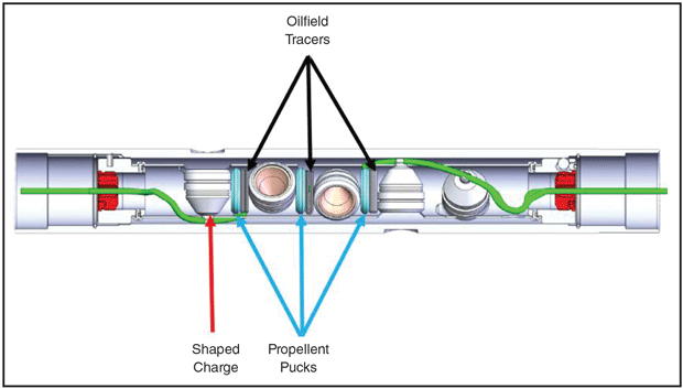
The same family of liquid oil and water tracers that is pumped into the flow stream during surface injection also is used in PGT, but they are in a solid phase inside of the perforation gun. Instead of a pump, PGT uses propellent to generate high pressure and high velocity gases to inject the tracers out of the perforation gun and into the formation only milliseconds after the shaped charges detonate.
Figure 1 shows a schematic of a perforation gun used in PGT. The propellent also has secondary advantages due to the possibility of cleaning the perforating tunnel as well as extending microfractures and conductivity beyond the perforation tunnel and into the formation and assisting with a higher likelihood of cluster breakdown.
FIGURE 1
PGT Perforating Gun Schematic
Propellants historically have been used in oil and gas completions to help stimulate the reservoir rock. Most common propellants generate a significant amount of gas pressure that burns an order-of-magnitude slower than the explosive detonation from the perforating event. This allows the generated gas pressure to be directed out into the formation through the pathway of the perforation tunnel. The forces generated by the propellant allow for the reservoir to be fractured as the pressure overcomes the stresses within the formation itself.
However, the main challenge with propellants in perforating completions is evaluating the optimal propellant loading for the reservoir. There is a balance between time and pressure. Different propellants provide different burn rates and pressures to benefit a variety of formation types. For many operations, care is taken to evaluate the completion as a whole to ensure the perforations and stimulation work together for the optimal results.
Testing And Proof of Concept
In order to evaluate a new technology where the tracer material is delivered simultaneously with the perforating event, several variables had to be evaluated. The first test conducted was evaluating if the tracer material would withstand the extreme pressures and temperatures created by the energetics in a perforating system. It was conducted by placing the PGT system in a closed vessel. The system was detonated in a controlled vessel and the propellant subsequently initiated.
After the test, the water surrounding the vessel was sampled for analysis of water tracers used in the PGT system. The lab analysis validated that there was a sufficient amount of tracer material detected in the water sample after the ballistic event, providing a positive indication that the tracer material survived the pressures and temperatures.
A second test evaluated the perforating system’s ability to be successfully deployed with all the constituent materials of the propellants and tracers. Full gun systems were loaded with perforating charges, propellant and tracer. The perforating guns were placed inside sample pieces of wellbore casing and detonated in a fashion that replicated downhole conditions. After the test was complete, the perforating guns were recovered and analyzed. Swell measurements were taken to verify that the nominal outer diameter of the carrier was acceptable to manufacturer standards. Next, the exit holes in the gun carrier were measured to make sure there were no visible issues with the perforating charges. No issues were found with the system during this test.
The final test of the perforating gun was evaluating the delivery mechanism of the tracer material. There were several designs for the tracer material packaging for deployment within the perforating gun. Some of the designs were more difficult to rapidly change and make compatible with different perf gun configurations. For example, the initial tracer material was pressed into a puck, but the puck had a fixed volume and size. Another design placed the tracer material inside a hermetically sealed bag-like package that was flexible and easier to manipulate for different perf gun configurations. Controlled ballistic testing proved that the containment packaging was sufficiently consumed by the detonation event in the gun carrier. No significant debris was found from the gun carrier post-detonation. Additionally, there was no sign of exit holes being blocked or plugged from debris.
Following lab testing, preliminary field experimentation was conducted in production wells to provide proof of concept. The returns of water tracers injected with PGT were compared with the returns of water tracers pumped on surface into the same stages as a control. Each cluster in a traced stage used the same unique tracer to better compare with the surface injection water tracer. The control tracer curves and the PGT curves followed in trend, indicating that the system successfully has injected tracer without pumps on surface. The PGT system returns were lower in value because of the lower tracer injection volumes. This proof of concept provided the framework to move forward with other experiments and case studies for PGT.
Case Studies
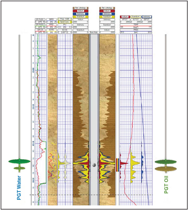
The first case study focuses on a pair of adjacent Marcellus wells in the Appalachian Basin. The operator wanted toe-side flow assurance diagnostics to be sure that the approximately two-mile long laterals were open to flow during flowback operations, and also for a period of about 50-60 days later when an adjacent pad was being fractured. PGT was used for every cluster in two stages in the toe-side of each well, with each stage having its own unique tracer.
Figure 2 provides a graphical representation of the PGT returns. Each curve represents the returns of the clusters from each stage. One interesting note is that the fracture driven interactions from the offset pad fracturing can be seen in the returns profile of the 1H well (and to a lesser degree the 2H) around 50-60 days from initial flowback. This area is highlighted to show that three of the four curves dropped below minimum detection levels from the offset pad frac water diluting the water returns from the 1H and 2H wells. However, after about 60 days, the tracers returned to detectable levels after the offset fracture communication stopped and no longer diluted the returns in the 1H and 2H.
FIGURE 2
PGT Returns Over Time
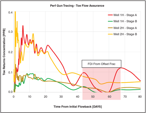
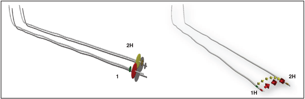
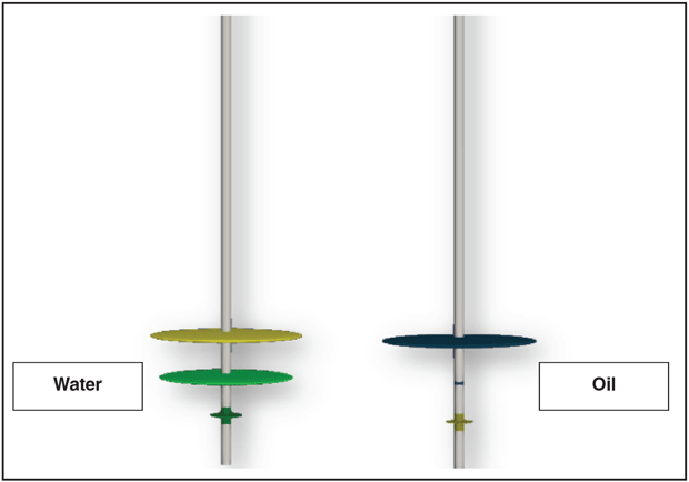
Figure 3 shows renderings of the returns profile (left) and well-to-well communication (right) of the 1H and 2H. The larger-diameter disks represent the clusters from the highest-returning stages. In addition, the arrows represent the clusters from the two stages that were in communication. Arrow diameter is proportional to the magnitude of communication. The colors of the well segments, disks and arrows correspond to the curves from the graph.
FIGURE 3
PGT Time-Weighted Average Returns (Left) and PGT Well-to-Well Communication (Right)
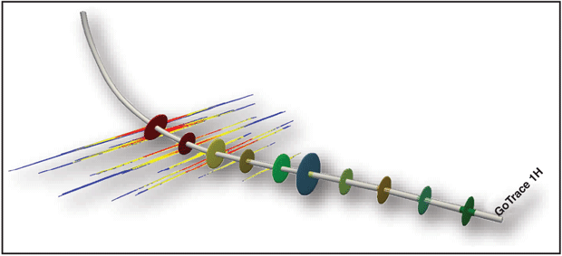
A Barnett operator utilized the PGT system to determine how deep the frac treatment fluids reached into the refractured lateral. The strategy was to squeeze off the original perforations in the well with cement and fire new clusters for the refracturing treatment using PGT perf gun systems in between the original clusters. In addition, proppant tracers were pumped into the refracture treatment on surface during the sand-laden fluid stages to see how far the proppant could be carried into the lateral.
The results of the PGT indicate that the fracturing fluids reached all the way to the toe-most new cluster in the well, which was about 1,300 feet from the heel cluster. The majority of the proppant however, only reached about half that distance, and was a likely result of lower-velocity fluids in the toe-side of the well. The proppant signature that was in the heel portion of the well did correlate well to the locations of the PGT clusters.
Figure 4 shows a rendering of the refractured well with the PGT water tracer returns represented as disks and the proppant tracer signature represented by the red, yellow and blue spikes.
FIGURE 4
Horizontal Refracture with PGT and Proppant Tracers
An operator in Oklahoma decided to utilize proppant, oil and water tracer diagnostics on a single-stage vertical well refracture treatment. The water and oil tracers were delivered directly into each of the two perforation intervals using PGT perf gun systems. A unique water and oil tracer also was used for each interval. Figure 5 shows a rendering of the tracer diagnostics. The proppant tracers were well distributed across the perforation intervals. The water returns were highest from the shallower interval and the oil tracer returns were about even between the two intervals.
FIGURE 5
Vertical Refracture with PGT and Post-Frac Temperature Survey
A post-frac temperature survey (red curve) shows that most formation cooldown (a result of cooler fracturing fluids on the formation) happened above the targeted perforation interval. Much less fracture growth below the intended perforation interval was evidenced by the rapid warm back to the geothermal gradient (blue curve) below the targeted perforation interval. The water, oil and proppant tracers indicated that the refractured interval was propped successfully and producing both oil and water from both intervals.
In the Permian Basin, an operator deployed PGT gun systems with both oil and water tracers to determine which intervals in a vertical well were responsible for the highest water and oil returns prior to a single-stage acidization treatment. Upon flowback, the shallow interval was responsible for the highest water and oil returns. Figure 6 shows the returns from the three-interval treatment. Since all of the intervals were subjected to the same acid treatment, the PGT diagnostics were able to determine which interval contributed the highest returns of water and oil tracer. This would have not been possible by batch tracing the acid on surface.
FIGURE 6
Acid Treatment with Oil and Water PGT
PGT provides a way to inject tracers down to the cluster-level of resolution. It is a highly versatile technology that can be used with perforation guns containing numerous combinations of number of holes, entry-hole diameters, shaped charges and phasing. It is especially well suited for scenarios such as refracturing or high-intensity perforating, where multiple open clusters of perforations are subjected to the same treatment fluids. Without PGT, a determination of which clusters are returning the most oil or water and which clusters may not be returning at all would require permanent monitoring hardware or an intervention for production logging.
In addition, PGT also can be used to obtain flow assurance, well-to-well communication and even FDI diagnostics. The tracers inside the PGT system are shelf-stable and can be stored and used when ready, and do not require a dedicated on-site representative.
Editor’s Note: For additional information on PGT technology or field applications, see SPE 210134, a technical paper presented at the 2022 SPE Annual Technical Conference & Exhibition.

CHRIS SQUIRES is the regional engineering adviser for ProTechnics, a division of Core Laboratories, in Pittsburgh. He works with operators to interpret the results of tracer diagnostic projects used to evaluate completions designs and hydraulic and hydrocarbon communication between wells. Squires started working in the energy industry in 2007 as an engineer for the cementing, fracturing and acidizing business units for Halliburton Energy Services in the Appalachian Basin. Squires then worked as the senior completions engineer for Consol Energy (CNX Resources) during the development of its early Marcellus and Utica wells. He holds a degree in mechanical engineering from Pennsylvania State University.

BRAD LEONARD is the regional sales manager for ProTechnics, a division of Core Laboratories. He began his career in 2007 as an account technician for BJ Services, advancing to account manager for the BJ Services’ chemical division in the Barnett Shale. Leonard joined ProTechnics in 2010 to manage all sales in the Dallas/Fort Worth area. During his 12-year career with ProTechnics, he has assisted numerous operators to better understand their completions by providing necessary solutions to increase their return on investment. Leonard is a graduate of Texas A&M University.

SHAUN GEERTS is the energetics engineering manager at Owen Oil Tools, a division of Core Laboratories. His 11 years of service at the company include perforation design, testing design and management roles. He holds a B.S. in mechanical engineering and M.S. degrees in explosives engineering and engineering management from the New Mexico Institute of Mining and Technology.

MATTHEW CLAY is the director of engineering at Owen Oil Tools. He began his career in 1996 as a ballistics technician for Schlumberger-Rosharon, and then joined Titan Energetics in 2001 as a shaped charge designer until 2006. His 16 years of service at Owen Oil Tools include engineering management roles in energetics engineering and ballistics engineering. He is a graduate of Texas State Technical College and LeTourneau University.
For other great articles about exploration, drilling, completions and production, subscribe to The American Oil & Gas Reporter and bookmark www.aogr.com.