


SCS Increases Production, Recovery
By Lukas Nader, David Biddick, Herman Artinian, Pandurang Kulkarni, Bob Van Hoy and Steve Zdan
CERRITOS, CA.–Despite their vast resource potential, liquids-rich shale gas reservoirs present unique challenges to production and reserve recovery, including high initial daily rates that decline rapidly as reservoir pressure depletes and long laterals that create complex wellbore trajectories that can make it difficult to lift liquids to the surface as reservoir pressure and gas velocity decline.
When the reservoir energy becomes too low to overcome total pressure losses in the production string, liquids drop out of the gas stream and accumulate in the well to form a hydraulic column. The backpressure generated by the liquid blockage in the wellbore or formation pore space inhibits gas production. The reduced gas flow diminishes gas velocity, which in turn, reduces liquid lift capability and allows more liquid accumulation in the wellbore/formation to further decrease gas production. This vicious cycle of liquid loading often causes wells to be abandoned prematurely because of economic factors before they reach their expected ultimate reserves recovery.
Artificial lift methods, such as positive and dynamic displacement pumps, help overcome liquid loading problems by adding mechanical, electric or hydraulic energy to the liquids in the production stream. Other artificial lift methods, such as gas lift, surfactants and demulsifiers, modify density, viscosity, surface tension, or other physical characteristics of the produced fluids. The subsurface compressor system (SCS) is a new form of artificial lift that can reverse the effects of liquids loading to increase gas and condensate production and extend economic well life.
The technology increases gas velocity at both the intake and discharge. The increased velocity carries more liquid out of the wellbore and reduces backpressure on the formation. Once liquids are removed and the well is unloaded, gas production can increase. The increased gas production will further increase gas velocity to carry more liquids up hole, simultaneously removing liquids, increasing gas and liquids production, and improving recoverable reserves.
Besides the higher gas velocity, subsurface compression raises the temperature of the discharged gas. Injecting this thermal energy into the gas stream promotes the evaporation of the liquids and/or prevents liquids from condensing, which also increases liquids lifting and reduces loading, and further increases the liquid carrying capacity of the gas rising to surface.
System Design
SCS technology has been developed with various diameters, power ranges and pressure ratios, but consists of three major components:
- High-speed permanent magnet electrical motor;
- Magnetic coupling; and
- Multistage hybrid axial flow wet gas compressor.
The four-pole motor has a maximum operating speed of 50,000 rpm. The rotor is levitated with passive magnetic bearings to support the high-speed rotating shafts without lubrication or a pressurized air source. The stator uses a proprietary insulation system to provide long life at high operating frequencies. The hermetically sealed, low-pressure housing contributes to an expected motor operational life of 20 years minimum. Similar to electric submersible pumps, multiple motor modules can be added in tandem to increase the system’s available horsepower. Each module is rated to 150 hp, which has proven more than sufficient in all 5.5-inch casing gas well applications analyzed to date.
The magnetic coupling transmits torque from the motor to the compressor through a solid pressure barrier, eliminating the need for any type of rotating seal. Magnetic couplings are commonly used for topside pumps in the chemical industry, but this is the first high-speed downhole application. The female end of the coupling is attached to the motor, with an isolation cup hermetically sealing it within the motor body. The male end connects to the compressor.
The key advantage of the proprietary compressor design is a relatively straight flow path compared with centrifugal compressors. When the flow path is straight with little change of direction, the heavier constituents–including liquids and solids–follow the gas phase because there is little centrifugal force to separate the high-density and low-density phases. Six stages of impellers provide a 1-to-1.45 pressure ratio. The design allows for a fairly flat compression curve and a wide operating range through the speed range.
FIGURE 1
Top Level Well Completion with Subsurface Compressor
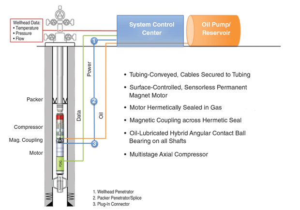
The complete compressor module is made of a nickel-chromium-based superalloy for the highest downhole integrity. The compressor shaft is supported with a proprietary hybrid angular contact ball bearing system that uses a minimal amount of continuous oil from the topside to ensure proper lubrication and prevent outside particles from entering the bearing cavity. The remainder of the system is similar to an ESP. A control center houses a variable speed drive, transformer, system level controller and monitoring equipment. Conventional ESP cables transmit power down hole to the SCS, and are clamped outside the production tubing as with an ESP (Figure 1).
Conventional Reservoirs
In conventional reservoirs, downhole compression increases recoverable reserves by arresting the production decline rate, postponing liquid loading and providing lower abandonment pressure (Figure 2). The SCS increases gas production by decreasing bottom-hole flowing pressure and enabling higher reservoir drawdown. Maximum drawdown can only be achieved by downhole compression near the perforations, where the gas is denser because of the hydrostatic forces.
FIGURE 2
Increased Production and Reserves with SCS
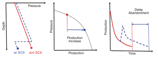
FIGURE 3
Subsurface versus Wellhead Compression Comparison
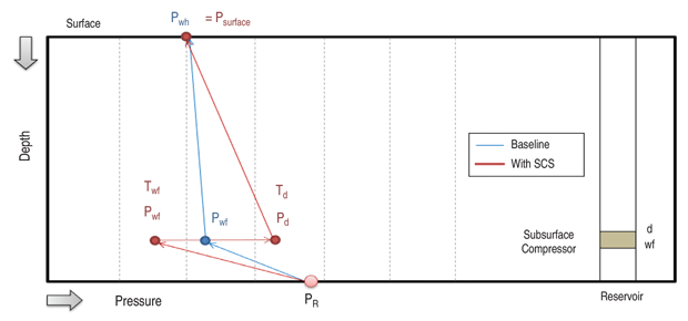
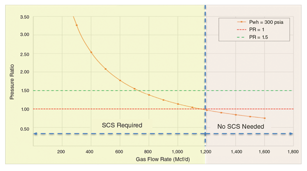
FIGURE 4
Pressure Ratio versus Gas Flow Rate
Operating a subsurface compressor in a gas well creates a low-pressure zone at the compressor inlet at the bottom of the wellbore to lower bottom-hole flowing pressure. These suction effects actively induce more gas flow from the formation into the wellbore. Deep, liquid-rich and high-rate flowing wells with friction dominated tubing flow and operating with relatively low drawdown are well suited for the downhole compression.
Furthermore, the SCS increases incremental well productivity in wells with higher liquids-to-gas ratios by directly creating drawdown on the formation without the pressure drops associated with gravity head and pipe friction losses. This means larger mass flow rates can be achieved for the same outlet pressure.
Similarly, low-pressure wells are very sensitive to viscous and kinetic pressure effects. In depleted reservoirs, a small increase in pressure drop can reduce the upward gas velocity below the critical value. Therefore, smaller-diameter tubing is required for efficient liquids removal, even though larger tubing would provide a higher flow rate temporarily.
The boosting effects with the compressor’s higher discharge pressure increases the wellhead pressure to facilitate the flow of gas into the surface gathering system. Without downhole compression, for the gas to flow from formation to wellhead, formation pressure must be higher than downhole pressure, which in turn, must be higher than wellhead pressure. With an SCS, downhole pressure does not need to be higher than wellhead pressure as long as the compressor’s discharge pressure is high enough to force the produced gas up the hole. Therefore, the well can produce gas from the reservoir under the lowest possible downhole pressure, or even on vacuum.
Another benefit is illustrated in Figure 3, which describes the process between the downhole gas compression and the wellhead gas compression on a chart of gas pressure along the depth. In highly depleted wells, the wellhead compressor experiences lower dynamic pressure at the compressor intake because of the pressure drop along the depth from the bottom hole, creating much lower density and higher volumetric flow that prevents the wellhead compressor from working efficiently. However, the downhole dynamic pressure at the compressor intake is much higher, with the higher density and higher mass flow subsurface compressor helping continue gas production even in depleted wells.
Unconventional Reservoirs
The benefits that can be achieved with an SCS in conventional gas wells also apply to liquids-rich unconventional gas wells. In long horizontal sections, trajectories undulate in a series of shallow peaks (filled with gas) and troughs (filled with liquids) that can lead to erratic and intermittent production, sluggy and turbulent flow behavior, increased liquid holdup, reduced hydrocarbon production, and premature well abandonment.
Moreover, in a multiphase reservoir system, gas will travel faster than liquids, and the holdup will increase over time. At low flow rates, the in situ density of the fluid mixture will approach the liquid density because of the excessive slippage, and the well will start to flow in an oscillating mode, often followed by severe liquid slugging.
The liquid fallback promoted by liquid loading exerts backpressure on the reservoir and increases pressure losses near the wellbore region by altering relative permeability and fracture morphology. Under this condition, produced liquids accumulate in the wellbore and further decrease gas production and accelerate the time until the well can no longer produce and needs to be prematurely abandoned.
SCS technology provides a novel solution to the combined challenges of liquids in the horizontal wellbore and in the formation. The increased reservoir drawdown by the subsurface compressor actively induces more mass flow rate from the formation to the wellbore. With the higher gas flow rates and lower bottom-hole flowing pressures, increased gas stream velocity carries more liquids out of the vertical and horizontal sections.
Figure 4 illustrates the pressure ratio needed to achieve a superficial gas velocity of 20 feet/second in a liquids-rich Marcellus Shale well. The red dotted line represents a pressure ratio of 1.0 without downhole gas compression. The green dotted line represents the pressure ratio of 1.5 with downhole gas compression, where the discharge pressure at the outlet is 1.5 times higher than the pressure at the inlet. Based on the 20 feet/second superficial gas velocity criterion, the minimum gas flow rate required to successfully remove liquids from the horizontal section would be 1,200 Mcf/d and without downhole gas compression. With SCS, however, the minimum flow rate for effectively sweeping liquids would be reduced by more than 40% to 700 Mcf/d.
The injection of thermal and kinetic energy into the gas stream increase enthalpy at the compressor discharge to promote liquids evaporation and suppress liquid dropout at the wellbore, which delays liquid loading and allows the gas stream to carry more liquids. An additional benefit is the higher lift efficiency facilitated by the reduced pressure drop around the wellbore. As reservoir pressure declines, the water saturation of the gas increases. The net effects are lower residual water saturation near the wellbore and reduced capillary imbibition in the pore space.
Condensate blockage inside the wellbore, near the wellbore, and inside the reservoir pore space can significantly reduce well productivity and impact ultimate gas and condensate recovery. This phenomenon is particularly important in liquids-rich unconventional gas reservoirs, where the ratio of the pressure drop in the hydraulic fracture to the total drop within the reservoir can be significant. Achieving the required in situ pressure ratio to overcome capillary effects and mobilize reservoir fluids from static equilibrium allows operators to extract greater value by increasing condensate production from their liquids-rich gas wells.
Shale Well Field Trial
SCS technology was deployed for the first time in an unconventional reservoir application in a horizontal New Albany Shale gas well in Indiana owned and operated by Riverside Petroleum. The field trial ran for roughly six weeks with the objectives of:
- Increasing gas production from a horizontal liquid-loaded gas shale well;
- Reducing downhole flowing pressure and creating higher reservoir drawdown;
- Improving liquids lifting efficiency by creating higher gas velocities throughout the vertical and horizontal sections; and
- Preventing liquid condensation by increasing the temperature of the gas.
The well has a 2,000-foot vertical section and a 5,000-foot horizontal lateral, where liquids had accumulated (Figure 5). The compressor was installed at the bottom of the vertical section with a tail pipe extending approximately 1,000 feet into the horizontal section to provide sufficient velocity to carry liquids while minimizing friction losses. A shroud was used to carry the extended length of the tail pipe. Three downhole memory gauges collected pressure and temperature data.
FIGURE 5
Well Geometry and Configuration
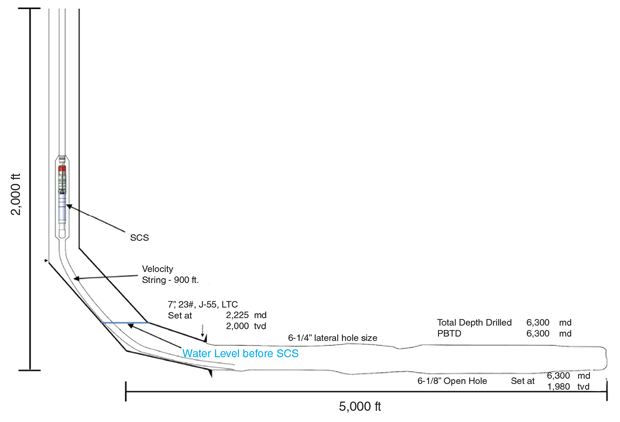
FIGURE 6A
Gas Velocity at 20,000 rpm
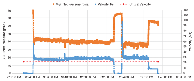
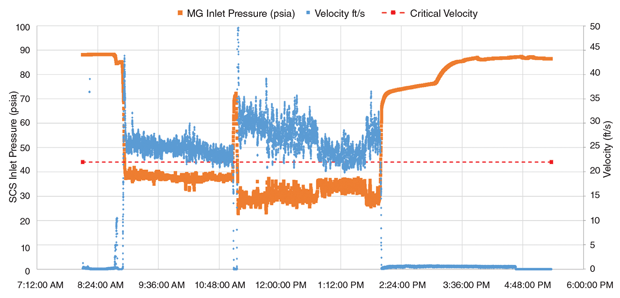
FIGURE 6B
Gas Velocity at Varying Inlet Conditions
Prior to installing the compressor, the well had been producing 179 Mcf/d and its liquid production (using a rod pump) was 5-7 bbl/d. Without the rod pump, the well choked within a few hours. The SCS field trial demonstrated an increase in gas production ranging from 34.1% to 67.5% over the 179 Mcf/d baseline. With the SCS operating at 30,000 rpm, the well stabilized at 300 Mcf/d.
The minimum required gas velocity to lift liquids to the surface is 22 feet/second. While the SCS operated at 20,000 rpm, the gas velocity within the vertical wellbore was 22.5 feet/second, and the well operated in the transitional state between slug and annular-mist flow conditions. The liquid production at the surface during that time was detectable, although intermittent (Figure 6A). The gas velocity was slightly higher than the calculated critical gas velocity until the SCS was turned off. Once the SCS was off, the intake pressure increased to 65 psia, which caused velocity to drop to 9 feet/second, far below the critical velocity.
When the SCS was operated at or above 30,000 rpm, gas velocity increased to 29 feet/second, and a high rate of liquid was carried to the surface (Figure 6B). The hybrid axial compressor was able to atomize the liquid into a very fine mist, which together with the increased velocity and heat generated from the exit of the compressor, helped carry the liquids to the surface.
The injected thermal energy into the gas stream promoted the evaporation of liquids, which also increased the liquid lifting efficiency and reduced the condensation of the liquid inside the production tubing. Water content, due to temperature effect in the gas stream, increased by more than 100% from 1.30 to 3.24 bbl/MMcf at the discharge of the SCS. The temperature of the discharged gas from the SCS increased by 27.5 degrees Fahrenheit due to gas compression.
As the Indiana well demonstrates, a subsurface compressor can replace the vicious cycle of liquid loading and reduced gas production with a “virtuous” cycle of liquid unloading and increased gas production. The increased gas stream velocity and liquids evaporation reduces liquid loading to effectively sweep more liquids and increase gas production.
LUKAS NADER is a petroleum engineer at Upwing Energy. Nader holds a technical degree in power engineering from the Northern Alberta Institute of Technology and a B.S. in petroleum engineering from the University of Alberta.
DAVID BIDDICK is project director at Upwing Energy. He holds a B.S. in mechanical engineering from the University of Wisconsin-Platteville.
HERMAN ARTINIAN is president and chief executive officer of Upwing Energy. He holds a B.S. in aerospace engineering from the UCLA.
PANDURANG KULKARNI is principal technology engineer at Equinor in Austin, Tx. He holds a bachelor’s in chemical engineering from the University of Mumbai, and a Ph.D. in chemical engineering from the University of Texas at Austin.
BOB VAN HOY is chief operating officer at Riverside Petroleum in The Woodlands, Tx. He holds a B.S. in electrical engineering from Purdue University.
STEVE ZDAN is chief geoscientist in the evaluation of oil and gas investment opportunities in North America for Riverside Energy Group. Zdan holds a B.A. in anthropology and an M.S. in geology.
For other great articles about exploration, drilling, completions and production, subscribe to The American Oil & Gas Reporter and bookmark www.aogr.com.