


Artificial Lift Experts Leverage New Insights To Build Tougher Systems
By Colter Cookson
Artificial lift engineers have a seemingly endless task list. There is always another well that could use attention or an optimization that could be performed given infinite time and resources.
However, in the real world, engineers must prioritize, sacrificing some otherwise appealing opportunities to focus on those that have a bigger impact on the bottom line. While infinite time is confined to fiction, the industry is discovering clever ways to free engineers from tedious tasks.
In some cases, greater freedom to tackle more challenging tasks comes from more reliable equipment that can turn once-troublesome wells into steadfast producers that rarely require workovers. In other cases, advanced software tools make diagnosing and troubleshooting problems, or planning future wells, a snap.
Take, for example, the common task of designing a rod pump for a horizontal well. Thanks to a decade-long research and development effort, this process may soon benefit from a mathematical model that more precisely predicts how a given pump will behave in a horizontal well.
“We have seen cases where our new model is 40% more accurate than the traditional wave equation, which was originally developed for vertical wells,” reports Peter Westerkamp, Lufkin Industries’ vice president of global sales for automation.
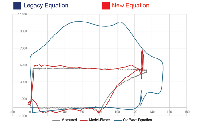
Lufkin Industries has introduced a mathematical model for rod pump systems that is up to 40% more accurate than the wave equation traditionally used to generate pump cards. The company says the new model, which accounts for mechanical friction and other forces that have become more significant as the industry has moved from vertical wells to horizontals, will help operators right-size equipment and improve pump-off control.
That extra precision comes largely from the new model’s ability to account for mechanical friction, a factor that the classic wave equation ignores. “In a vertical well where the wellhead is directly above the pump, ignoring mechanical friction makes sense because there is hardly any of it downhole,” Westerkamp acknowledges. “The engineer primarily needs to worry about the weight of the rod string and fluid, some of the dynamic effects on the rod string, and hydraulic friction.
“But if the well is deviated or horizontal, the rod string will begin to slide against the tubing, creating mechanical friction that causes drag loads in the system,” he says. “To overcome that friction, the surface equipment needs to be larger.”
This is not a theoretical concern. “We have examples where traditional design tools underestimate the load on the system and recommend operating the pump with a variable frequency drive and motor that did not have enough horsepower for the application,” Westerkamp reports.
He adds that those tools’ friction blind spot causes them to overstate the length of each pump stroke. “If the stroke downhole is significantly shorter than expected, the well will have to pump faster than intended, which increases horsepower requirements and causes extra wear and tear on the system that can shorten the time between workovers,” he comments.
In addition to addressing these issues, Westerkamp says the new mathematical model can make pump-off control far more effective by generating more accurate pump cards. “Under normal operating conditions, an accurate card should look rectangular,” he notes. “However, since horizontal drilling began, we have seen pump cards with all kinds of curves and wobbles and shapes, because they were generated using an equation that had become out of date.
“The pump card is supposed to tell the controller when fluid is available,” he says. “If it’s inaccurate, we may end up pumping when there is too little fluid, which wastes energy and damages the pump. Or we may end up in the opposite scenario, where we give up production by lowering the speed or stopping the pump when there is plenty of fluid to produce.”
Thorough R&D
Lufkin began developing the more accurate model in 2014, Westerkamp recalls. Rather than relying on theoretical assumptions to create it, the company designed and deployed downhole tools to collect data in actual wells.
Westerkamp expresses pride in Lufkin’s commitment to the project, which required significant time and money. “We are the only service company that has made an internal investment to update the wave equation and validate the results with field data,” he says.
Field data matters, Westerkamp says. “While running the tools, we noticed some downhole conditions that we would not have considered otherwise,” he explains. “For example, it’s very common to install rod guides to minimize the mechanical wear between the rod string and tubing. During tests, we realized how much the turbulence in the fluid around those rod guides affects the pump card, so we adjusted our mathematical model to account for turbulence.”
Such discoveries would not have been possible without the cooperation of operators who allowed Lufkin to run its tools in a variety of well types, including vertical wells, slightly deviated ones and true horizontals, Westerkamp notes. “In many wells, we went in with at least two or three different downhole completions to compare information,” he mentions. “For example, in one well, we ran a pump with a given clearance. Then we ran back in with the exact same completion but reduced the clearance so we could learn how the downhole stroke reacted to the tighter fit.”
The company also compared strings with and without rod guides, then varied the guides’ coefficients of friction to see how that affected results. It also investigated how different sinker bar counts influence the stroke, as well as how steel sucker rods differ from fiberglass rods.
To turn the vast amount of information it collected into a sound mathematical model, Westerkamp says Lufkin worked with mathematical experts at Texas Tech University. “It’s been a long process,” he reflects. “It was far more complicated than we expected it to be, but now we have a model that is much stronger than the one we had before.”
On wells with Lufkin’s current-generation well manager, operators can begin using the new model to inform pump-off control by updating the software, Westerkamp says. For wells with the older well manager, the company offers an upgrade kit.
“We have just launched the new model, but we think the payback on deploying it will be 6-12 months,” he says.
Streamlining Optimization
At many companies, production engineers now oversee hundreds of wells, observes Chris James, director of product for Xecta. “It’s impossible for them to fine-tune every one of those wells, so they need a practical solution that identifies the wells they should focus on,” he says.
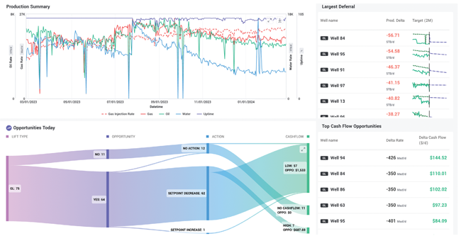
By using modern software architecture and optimizing processes as much as possible, Xecta reports it has developed an artificial lift optimization platform that can model each well quickly and accurately. This speed allows the platform to identify opportunities to improve well economics, then sort those opportunities by their impact to help engineers prioritize work.
To help production engineers prioritize work, James says Xecta has developed a platform that models all the wells to find the ones most worthy of attention. “When production engineers come into the office in the morning, it only takes five minutes for them to determine which five or 10 wells they need to analyze that day,” he says. “When they start using the platform, these tend to be high-value wells that have slipped through the cracks because of time or resource constraints.”
With the right tools, such prioritization can be extremely valuable, James says. “One of our customers is seeing a 3%-5% uplift in oil production from gas lift wells,” he illustrates. “When a field produces 600,000 barrels of oil a day, even a 3% gain has a substantial impact on revenue.”
To identify the high-priority wells, James says the platform models every element of a well, from the reservoir to the surface. “We’ve got a reservoir model that can calculate reservoir pressure over time. We’ve got a bottom hole pressure model that will calculate downhole pressures each day, and by proxy, a lot of artificial lift diagnostics. From there, we get productivity index every day on each well to analyze and measure performance.
“There is a lot of anomaly detection and diagnostic information, both about the artificial lift and the operation,” he adds. “That could be something as simple as downtime trends or wells that are seeing unusually high gas-to-oil ratios or water cuts, all the way down to a potential stuck gas lift valve, a hole in the tubing, an ESP that is flowing up the backside, or a rod pump that is seeing rapid fillage declines.”
These diagnostics can be extremely accurate, James assures. For example, he says he’s heard stories from engineers who have pulled an underperforming well that Xecta warned had a hole in the tubing. “When the company sent us pictures, the hole was within 20 feet of where we estimated it would be,” he says.
In addition to diagnosing problems, the platform will make recommendations. For example, it can suggest changes to injection rates on a gas lift well or changes in frequency on an electric submersible pump that should improve production or reduce costs.
The Next Step
As engineers use the platform to transform most of their wells into reasonable performers, James says they increasingly find time to think about bigger-picture issues. “An engineer that now has three or four hours a day that were previously occupied with busy work can now spend time improving future wells by modeling different scenarios,” he says. “For example, a lot of companies have an artificial lift recipe that they default to for every well. They might flow the well back, put it on ESP until the first ESP fails, then switch to gas lift until they hit 100 barrels a day, at which point they will move to rod pump.
“We have a lot of tools that allow people to run simulations across hundreds of wells to investigate whether their recipe is the best strategy,” he says. “In some cases, they may realize they do not need a recipe at all. Instead, they can tailor the artificial lift selection to each well.”
To look at hundreds of wells and make sound recommendations, the platform needs to model each well quickly, James notes. “In our service-level agreements, we commit to modeling wells in less than 10 minutes,” he says. “Right now, we are averaging less than two minutes.
“When people hear how quickly our models run, they think we must be sacrificing accuracy,” he acknowledges. “But that is not the case. The platform is fast because we built everything from the ground up using modern, cloud-scalable architecture, then optimized every process into oblivion.”
That optimization is no joke, he says. “We have some algorithms that are extremely computationally intense, such as ones for monitoring reservoir pressure,” he says. “To achieve the performance we needed during model development, it sometimes took days or even weeks of a few experienced software engineers analyzing every line of code and questioning whether each task could be done more efficiently.”
AI’s Role
AI can be a powerful tool, but it is one that needs to be deployed carefully, James says. Noting that Xecta’s founders came from the technology and research group at Anadarko Petroleum Corp., he says the company has the expertise to use AI smartly.
“We are not one of the Silicon Valley-type startups that is coming into the oil and gas industry and hoping to change it using pure AI,” he says. “I do not think that works for artificial lift. If you are going to model an ESP well, you need to estimate the pressure generated at the pump downhole. For gas lift, you need to know the pressures that will cause each valve to open or close. There is no AI substitute for basic physics.
“But there are many areas where AI can augment basic physics and we end up with a hybrid model,” he says. “One example would be bottom hole pressure. As we’re calculating the pressure profile throughout the well to understand what is going on downhole, the industry standard is to use a multiphase flow correlation. There are several on the market or in the literature, such as Hagedorn and Brown or Duns and Ros, but it can be hard to tell which one is the most appropriate for any given well. Finding out usually takes trial and error.”
That is where AI steps in. “On some wells, we’re lucky enough to have gauges that allow us to compare a flow correlation’s physics-based approximation to the gauge’s hard data,” he says. “By running this comparison for every correlation, we can tell which one is the best fit for each well with gauges. Then we can train an AI model that selects the best correlation for any well based on its location and properties.”
Once the AI model selects the right correlation, its output will feed back into physics-based modeling for the artificial lift system, James says.
As with any optimization effort, it is vital to provide high-quality data. “We have built an entire data platform that is extremely flexible and can read from company sources, such as various cloud data lakes,” he says. “We also have a robust suite of both rule-based and AI-driven data quality algorithms that will identify all the places where we know the data quality is poor. As an example, it will spot if a well has a gas lift injection rate but no information on the gas lift valves, or highlight a tubing top depth that is negative 1,000 feet because somebody punched in the wrong number.”
Connecting with and cleaning up data takes time and some work on the operator’s part, but James says that work can be done quickly. “For one of our customers, we have onboarded four assets that each contain 1,500-2,000 wells in 30 days for each asset,” he reports.
Strengthening Conversations
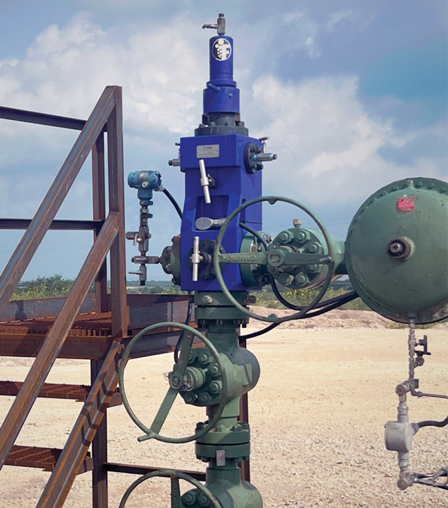
When wells convert from ESP to rod pump, the transition can result in significant losses in oil production, says Gustavo Gonzalez, chief executive officer of Odessa Separator Inc. (OSI). This problem is caused by high gas production associated with the liquids and can lead to several operational and financial difficulties for operators. “We have developed a system that uses a secondary separator to boost separation to the point that the well will maintain or even gain production after switching to rod pump,” he reports.
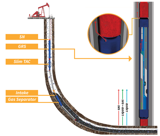
Even a well-designed and properly-placed gas separator will leave some gas entrained in the liquid. To stop as much of that gas as possible from reaching the pump, Odessa Separator has developed a secondary separator (here labeled “GRS”) that releases most of the gas. In numerous field trials, this separator has allowed operators to boost or maintain production after transitioning wells from ESP to rod pump, the company reports.
In production configurations that use the system, the primary gas separator is placed at 40-60 degrees in the curve, where liquid tends to build. “The idea is to have all the equipment submerged in liquid and a large flow area for gas to pass around,” Gonzalez explains. “This reduces the amount of gas that the primary separator needs to handle.”
Even with that best practice, some gas will remain entrained in the liquid. Once the liquid passes through the primary separator, a velocity string carries it upward and into a proprietary secondary separator. There, differential pressure allows gas to escape upward while gravity and the tool’s geometry force liquid to fall downward. Ultimately, the liquid ends up in the pump while the gas travels up the annulus and away from the pump, Gonzalez describes.
“We are essentially enhancing the downhole gas separation process by using multiple mechanisms for separation,” he says. “The primary separator is in the curve, and then the liquid enters the secondary separator, which releases most of the remaining gas.”
Since the system’s introduction two years ago, it has gone through three iterations and been deployed in more than 450 wells, Gonzalez reports. “With the third-generation design, we have a 90% success rate,” he says. “Success means that the production rate increases or is the same after the conversion from ESP to rod pump.”
The production gain can be substantial, Gonzalez says. As an example, he points to a well where the liquid and gas production rates had been falling in the month before it converted from ESP to rod pump. After that, oil production increased 54% and total liquid production went up 50%. This case study is one of six in “Insights and Results from New Applications of an Enhanced Gas Separation Method for High-Fluid, High-GLR Horizontal Rod Pump Wells,” a paper that ConocoPhillips, Diamondback Energy and OSI presented at this year’s SWPSC.
The cost for the enhanced separation is low, Gonzalez assures. “The cost varies from well to well, because if the well is deeper, it may need more tubing, and if the well is producing a high amount of sand, we may need to do something to manage that sand before the liquid and gas reach the primary separator,” he says. “However, many wells can pay back the cost in a day, or at most, a week.”
Gonzalez adds that the proprietary separator has potential beyond conversions. “We have begun doing trials with clients on using the enhanced gas separator on the second or third ESP, where gas can be a big problem,” he shares. “Our goal is to prolong the life of the ESP without affecting pump performance. If we can keep the ESP running for five additional months and delay the workover operation, it will be a complete win for the operator.”
Gas Lift Valves
As gas lift has become increasingly popular in horizontal wells, valves have become a focal point for many operators, says Daniel Murski, a technical sales expert for gas lift at Liberty Lift. “A couple decades ago, if a valve failed, companies would often pull it without spending too much time thinking about the cause,” he says. “But today, many operators take the time to look at the recovered valve and try to figure out why the failure occurred.”
Several factors can make valve failure more likely, Murski notes. These include heat, which can deform the elastomer seals that protect the valves; sand, debris and other contaminants; and excess pressures, which have become more common in some areas because of offset frac activity.
To mitigate these risks, Liberty Lift has introduced a gas lift valve that combines redundancy with fault tolerance to achieve long life. More than 6,500 of the valves have been deployed, Murski tallies.
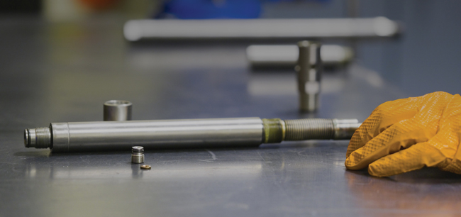
This enhanced gas lift valve includes extra seals and other mechanisms designed to protect the valve and prevent valve-related issues from compromising the gas lift system.
“We started running the robust valves in May 2023, so we’ve had numerous completions that have been in the ground for almost two years without any issues,” he says. “We have not had any reports of a well needing to be pulled because one of the robust valves failed.”
This is a huge step forward for many operators’ gas lift programs, Murski remarks. “In some areas, conventional valves can fail three or four weeks after installation. Sometimes the same designs will last two or three months, or maybe longer depending on conditions. Their longevity varies, but when we do the root cause analysis, we often find that elastomers have failed. With the more robust valve, we have found operators are no longer seeing those issues.”
Liberty’s valve lasts longer partly because it has more protection built in. In contrast to a standard injection pressure-operated valve, which uses two elastomeric seals and a metallic gasket to prevent its bellows from losing pressure and one elastomeric seal and a metallic gasket to guard against outside pressure intrusion, the robust valve contains four elastomeric seals, one metallic gasket or washer, and a metal-to-metal seal designed to trap any pressure that is looking to escape. The valve also contains five elements safeguarding against outside pressure intrusion: the metal-to-metal seal, three elastomeric seals, and a metallic gasket or washer.
The extra seals are only part of the equation, Murski says. The other half is minimizing the severity of any pressure loss or gain if one of the seals gets damaged. “For example, on top of the valve core, where a tail plug essentially screws into the dome adapter, there is normally a large void area remaining following final torque, which extends the allowable bellows area. We shrunk that area as much as we could to reduce the effective magnitude of any pressure loss beyond the valve core.”
Most gas lift systems include a safety factor of 20-25 psi to account for any pressure variations, Murski mentions. “With the new valves, volumetric calculations put the maximum pressure loss at about nine psi,” he says. “That loss is small enough that its unlikely to be extremely detrimental to the successful operation of the gas lift system. The system will continue to function with minor pressure variation.”
For a detailed description of the valve’s design, download “Robust Gas Lift Valve with Multiple Seals Suitable for Harsh Environments,” a paper that Murski presented at this year’s Southwestern Petroleum Short Course, which was held April 21-24. All the papers from the event are available for free at www.swpshortcourse.org.
In many areas, Liberty now defaults to recommending the robust valve, Murski says. “Early on, we would run the valve in wells that had particularly high bottomhole temperatures but stick to conventional IPOs in wells with lower temperatures,” he recalls. “However, temperature is not the only reason valves fail. It’s often a combination of factors, such as exposure to chemicals and various other well conditions. That has pushed us to standardize on the safer valve.”
Widespread use has become easier as Liberty has streamlined its manufacturing process and brought the premium for the more reliable valve down, Murski says. “Most operators are more than happy to pay a couple hundred dollars more for a valve if it means preventing a $40,000 workover.”
Adaptable Wellhead
Improvements in plunger design and increasingly widespread plunger lift expertise have enabled the artificial lift technique, which was once reserved for wells that produce less than 20 barrels of liquid a day, to excel in applications with production rates as high as 750 bbl/d. According to Mitch Boyd, vice president of plunger lift for Flowco Production Solutions, operators and service companies will continue pushing plunger lift’s upper limits partly because of how well it complements gas lift.
“Because plunger lift uses gas as the energy for the plunger, it can be integrated with gas lift to improve efficiency, which shrinks the amount of gas that needs to be injected and the size of the compressors,” he says. “Plunger lift simultaneously mitigates paraffin by constantly cycling liquids, not allowing oil to cool, and using the plunger’s movement to scrape paraffin from the inner diameter of the tubing.”
As engineers’ desire to use plunger lift has grown, so has the number of voices calling for a simpler way to convert wells to plunger lift, Boyd says. In a traditional plunger lift wellhead, he notes, the lubricator sends the production to an external, assembled flow loop that is off to one side. In low-volume wells, that approach works fine because the flow loop can be installed quickly using threaded connections.
But as production volumes and pressures rose, the industry had to move from threaded connections to flanges. Today, switching to plunger lift usually involves taking apart most of the wellhead and using flanged connections with welding typically required to attach the external flow loop and reassemble the sales line, Boyd describes. Add in the need to verify the welds’ strength by conducting hydrostatic tests, and the installation can require several contractors and 8-10 hours of work, he relates.
By using a patented wellhead solution from Flowco, Boyd says operators can shorten the transition time to two hours or less. At first, this modular solution behaves like a standard flow block. However, the lower portion contains a removable blind flange. “When it’s time for plunger lift, the operator can simply replace the blind flange with a lower flow outlet assembly,” he outlines. “A single technician can do this by shutting the well in, depressurizing the wellhead, removing six bolts, popping the blind flange off and inserting the lower outlet assembly.”
A new wellhead solution for plunger lift can be installed in less than two hours, much faster than the 8-10 hours required for a traditional flanged lubricator wellhead, Flowco reports. The company adds that this solution can work like a standard flow block until plunger lift is needed, then switch to plunger lift mode through a simple operation that a single technician can perform.
Once that’s done, the block has transitioned to complete plunger lift functionality. According to Boyd, this solution is extremely versatile.
“The lower flow outlet assembly has an integrated variable choke, which allows the operator to adjust flow as the well’s conditions require,” he illustrates. “In contrast to external solutions, which may only have a ball valve that can be either open or closed, it is a fit-for-purpose design.”
The variable choke can be manual, electric or pneumatic, but for now, most operators go with manual. “The choke may only need to be changed periodically, but having the flexibility throughout the life cycle of the well to fine-tune lower outlet flow is critical for plunger optimization,” Boyd says. “With a traditional lubricator, the plunger cycle times have to be changed or an external solution installed, which adds cost or limits well optimization.”
If the well or an offset is about to be refractured, the operator can protect the plunger and wellhead by catching the plunger, then temporarily re-installing the blind flange to go back to flow block mode, Boyd mentions.
Flow Performance
Past attempts to integrate a flow loop into a flow block’s footprint have had limited success because they lacked the flow capacity to keep pace with the amount of fluid and gas that today’s plungers bring to the surface, Boyd says.
“As the plunger is arriving or sitting in the lubricator, we need to be able to displace the fluid and gas off quickly or the plunger will constrain well optimization,” he says. “With the modular wellhead solution, that is not a concern because its flow performance is greater than any other lubricator we manufacture. It beats the next-highest design by 35%.”
Boyd attributes that exceptional flow performance largely to the upper section, which contains three flow loops that merge into the lower flow block area.
“With a traditional lubricator, the production goes out one side into the external flow loop,” he says. “Inside ours, the upper section has three flow loops—two on opposite sides and one in the back—to give the gas multiple places to go. Combined with the lower outlet flow regime, this exhausts gas and liquids more rapidly.”
The multi-loop design also redirects any sand or debris the well makes across multiple paths, minimizing the risk material will build up and hang up the plunger at surface, Boyd adds.
The flow loops contain 90 degree turns, which he notes can concentrate wear. “At every turn, we integrated flanged variable orifice inserts to protect the block,” he says. “The flow goes through these inserts, so they take the wear.”
By rotating the flanges to shrink the orifices, operators can manage flow through the flow loops to slow the plungers’ ascent, which can be helpful if it is surfacing at speeds that will cause excess wear.
“Early in the life of the well, the orifices will likely be wide open,” Boyd says. “However, in gas-assisted plunger lift or plunger-assisted gas lift, the injection gas energy can sometimes cause rigid plunger impacts, especially as the well ages and the plunger is no longer carrying as much fluid. Managing flow within the integrated flow loop allows precise control of impact, an option we would not have with a traditional lubricator.”
Even when the orifices are open, Boyd says the modular wellhead solution can soften impacts. He points out that one of the flow loops in the upper block is slightly lower than the others, allowing gas to begin escaping earlier upon arrival, rather than spending its energy accelerating the plunger.
“We have more than 200 units installed. Most of them were put in late last year, so we do not yet have enough data to quantify how much of a difference the milder arrival impacts will make on overall tool life,” he says. “But on every well we’ve been on, when we listen to the plunger arrive, the impact is unbelievably quiet, compared to what we’re used to.”
For other great articles about exploration, drilling, completions and production, subscribe to The American Oil & Gas Reporter and bookmark www.aogr.com.