


Vapor Recovery
Best Practices Optimize VRU Results
By Jeff Voorhis
MIDLAND, TX.–Growing safety concerns, ever-more stringent emissions regulations and higher well counts with wellheads and production equipment in close proximity on multiwell pads have been key drivers in the industry’s increased adoption of vapor recovery technology on production sites. But from the operator’s perspective, there is another major incentive to recovering vapors: revenue capture.
A vapor recovery unit (VRU) is essentially a compression system that collects and compresses low-volume gas streams for injection into the suction of a larger compressor, a meter run, a local site fuel gas system, or directly into a sales gathering line. To appreciate the full benefits of vapor recovery, operators must understand that vent gas is a product that has value and is not merely a compliance issue. The value of capturing vent gas to route to the sales line or use to power facility operations instead of venting or flaring has been documented many times in VRU field operations.
Simply put, what a VRU does on a production site is capture waste gas emissions and convert them into a revenue stream while at the same time keeping workers safe and ensuring regulatory compliance. The proper design, operation and maintenance of these units is key to ensuring an economic payback that reduces emissions, liability and risk.
By recovering casing-head gas, volatile organic compound vapors from crude oil/condensate/produced water tanks, heater treater (separator) flash gas and glycol dehydrator still column vent gas, VRUs allow the operator to:
- Generate revenue by sending the high-BTU content recovered vapors to the sales pipeline to maximize a facility’s total gas sales volume;
- Reduce air emissions, since they recover vent gas that would otherwise be emitted to the atmosphere or burned in a flare; and
- Assist in meeting air permit limits and reduce current and future risks and liabilities associated with greenhouse gas emissions (including VOC/methane releases from storage tanks; leaks from valves, connections, flanges, seals, hatches and other equipment; glycol dehydration unit still column vents and flash tanks; and facility depressuring/blowdown).
FIGURE 1
Vapor Recovery Unit in Multiple-Tank Application
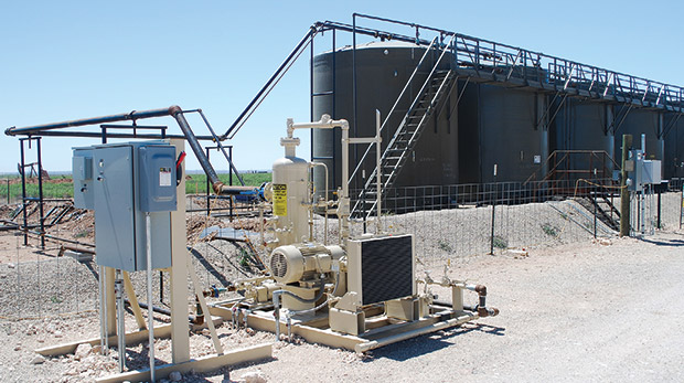
As shown in Figure 1, mechanical VRUs consist of an electric motor or natural gas-fueled engine that supplies power to the compressor, typically a flooded rotary screw or rotary sliding vane (reciprocating mechanical compressors also are used in dry gas applications). Mechanical VRU compressors work by squeezing the gas into a smaller volume, thereby increasing the pressure. Based on the ideal gas law, the pressure of the gas is inversely proportional to its volume, so the greater the decrease in the volume, the greater the pressure increase.
Variable frequency drives (VFDs) are used with VRUs to adjust the speed of the compressor driver based on the flow of gas into the unit. This increases the turndown ratio, which increases the operational range of the gas the VRU can recover effectively. Because VRU applications have relatively large fluctuations in volumes and pressures, the VFD provides a larger degree of operating flexibility for the overall system and allows the compressor to more quickly respond to increasing or decreasing flow rates into the VRU.
Recovering Tank Vapors
Given the multiphase nature of horizontal resource plays and the soaring production of associated gas from “tight oil” reservoirs such as the Wolfcamp and Bakken, one of the biggest application areas for VRUs is recovering vapors and flash gas in crude oil, condensate and water storage tanks at pad production sites and centralized treatment facilities.
FIGURE 2
Storage Tank Vapor Recovery Process Flow
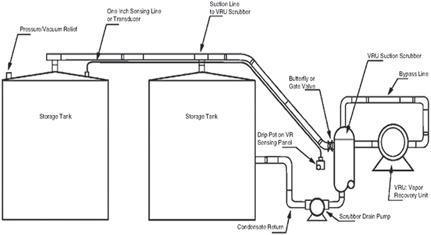
Controlling storage tank emissions can be complex, given the range of equipment and the number of dynamic variables affecting flow rates and pressures on a typical production site (Figure 2). Fortunately, the U.S. Environmental Protection Agency has issued a bulletin that highlights engineering and maintenance practices that can improve compliance and reduce VOC emissions from onshore storage vessels. While not intended as definitive guidance to achieve compliance with air quality regulations, the “compliance alert” does summarize proven best practices that oil and gas operators are using already.
The information in the alert was timely, considering that it was issued in advance of the EPA’s final rule on New Source Performance Standards (NSPS) for methane and VOCs (NSPS subparts OOOO and OOOOa), which was published in June 2016. The regulations cover emissions on both oil and gas well sites (including well completions and hydraulic fracturing, equipment leaks, pneumatic controllers and pumps, and storage tanks), production gathering and boosting stations, natural gas processing plants, and compressor stations.
The pace of federal air quality regulations to reduce fugitive methane and VOC releases from oil and gas operations has slowed. With the NSPS OOOO/OOOOa rules now in place, the focus for EPA and state regulatory agencies has shifted to active enforcement. The expectation is that EPA will continue to make storage tank emissions a priority in enforcement inspections. Implementing best practices can enhance compliance and improve negotiations with regulators should an operator have a compliance issue to resolve.
All new and existing facilities must be designed and operated to comply with the new rules, although facilities that existed prior to the applicability dates of NSPS OOOO/OOOOa are “grandfathered in” and have fewer emission control requirements. These grandfathered facilities can be opportunities to use voluntary options to reduce VOC and methane emissions. Also, many companies have GHG emission reduction goals that are used to voluntarily reduce fugitive emissions in their operations.
Best Practices
Specific engineering and maintenance best practices for recovering flash gas from liquids storage tanks identified by EPA include:
- Reducing liquid pressure prior to transferring the liquid to atmospheric storage vessels;
- Using adequate diameter piping for vent lines to emission control devices;
- Preventing liquids collection in vent lines;
- Eliminating unintentional natural gas carry-through;
- Ensuring proper maintenance and set points for pressure relief valves;
- Minimizing venting from thief hatches; and
- Adequately sizing emission control devices.
Operators should use multiple stages of separation to reduce flash gas volumes and peak vent gas flow rates during separator dumps of oil and produced water to storage vessels. This allows the system to operate with a smaller pressure drop between the last stage of separation (low-pressure separator/heater treater) and an atmospheric tank. Of course, to reduce air emissions, the gas liberated by the intermediate stages of separation must be recovered by a VRU and used either as fuel or sent to the sales pipeline rather than vented to the atmosphere.
Infrared optical imaging video cameras routinely are used to survey production sites to identify gas being vented to the atmosphere that is invisible to the human eye, validating volumes being lost. Infrared cameras also can be used to assess an oil and gas process to optimize pressure drops to atmospheric tanks and reduce flash emissions.
FIGURE 3
Vapor Recovery Unit in Single-Tank Application
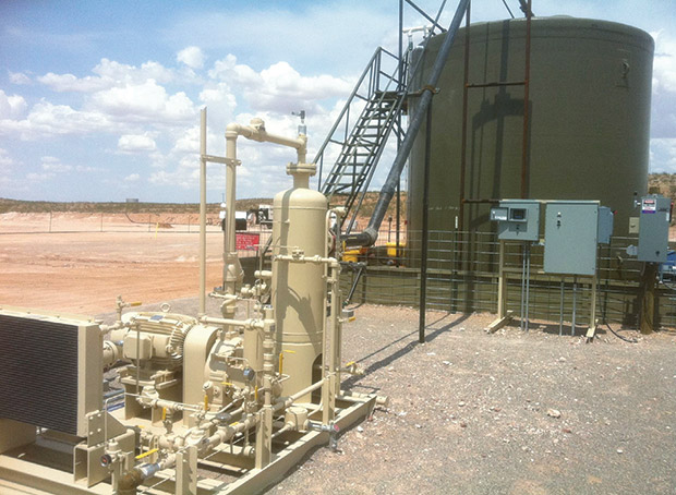
Vent piping between storage tanks and emission control devices must have a sufficient diameter to handle the potential instantaneous peak flow of vent gas (including flash gas) during separator dumps. If the piping is inadequate, a portion of the gas will not be collected by the VRU. This will increase the chance of creating backpressure on the storage tank and result in venting to the atmosphere at the thief hatches and/or pressure relief valves. Adequately sized vent piping should be a standard design criteria when sizing VRUs for a tank facility (Figure 3).
With respect to preventing liquids collection in vent lines, the efficiency of vent gas control systems will be reduced if rich gas in the vent line between the tank and emission control device condenses and collect in vent lines, especially in low spots along the path. An effective solution to this issue is using sloping piping of adequate inner diameter from the tank that is routed to a drip pot (i.e., scrubber) to ensure that liquids do not collect in the line and create blockages. Also, the scrubber can remove liquids that can harm VRU compressors and cause smoking conditions in enclosed combustors/flares.
Gas Carry-Through
Natural gas carry-through can be caused by pressure increase during normal separator dump events and also can occur when separator dump valves are stuck in open position (i.e., a valve failing to reseat and leaking gas into a tank). In this case, storage tank pressure relief devices will open and vent gas on a regular basis to relieve the increased pressure. If the repeated venting from pressure relief devices is not related to unintentional gas carry-through, the following corrective actions are recommended:
- Increasing the pressure relief device pressure set point if there is sufficient margin between the set point and the rated pressure of the storage vessel while continuing to safeguard storage vessel integrity;
- Taking steps to decrease the liquid pressure drop experienced at the storage vessel; and
- Replacing the tank with a storage vessel that is rated to a higher pressure and using higher pressure set points.
Facility design should take into account production rates and operating pressures in sizing VRUs. Again, infrared cameras can be used for onsite inspections for carry-through of vent gas caused by stuck dump valves.
By design, pressure relief valves are safety devices that protect vessels from over-pressurization and should remain closed during normal operations. They are not process vents that should discharge during normal operations. The EPA alert states that the valves should have a pressure setting that is low enough to protect vessel structural integrity and avoid overpressurization, but high enough to exceed storage vessel operating pressures during normal operation.
When a pressure relief valve is found to be venting to the atmosphere, actions should be taken to verify proper valve reseating after opening. For valves that are opening on a frequent basis, the operator should determine the cause. Actions to take can include increasing the pressure set point for the pressure relief valve (this requires an adequate safety margin between the set point and the storage vessel’s rated pressure), decreasing the operating pressures experienced at the storage vessel, and using a higher pressure-rated storage tank and a higher set point for the pressure relief valve.
Of course, the operator always must consider safety issues with any pressure relieving devices, including adjusting their operational settings. This is another area where infrared cameras can be used to inspect pressure relieving devices and thief hatches, and to measure and sample leaks.
Thief hatches and pressure relief devices should be inspected regularly to ensure good seals. Installing quality gaskets on thief hatches and regularly inspecting gaskets will ensure proper sealing. It is also important to implement procedures to ensure thief hatches are properly closed after vessel gauging, sampling and unloading.
With respect to proper sizing of emission controls, operators should ensure that vent gas control devices are designed for the specific facility’s operations. The design should be sized and operated to control for the full range of expected gas flow rates. Key to ensuring proper sizing of emission controls is appropriate sampling, measurement and modeling to estimate potential maximum vent gas flow from storage tanks. Process simulation calculations can be run to estimate the potential range of vent gas flow rates for various operating scenarios, and these assessments then can be used in sizing the VRU.
Other Recommendations
There are a number of other design and operating recommendations beyond the best practices listed in the EPA alert. For example, the flow rate of vent gas from the emission source should be measured whenever possible using turbine meters or thermal mass flowmeters in conjunction with infrared optical gas imaging cameras. Actual vent gas flow rate measurements are valuable for the optimal sizing, design and operation of a VRU by determining the minimum and maximum flow rates over a 12- to 24-hour period.
In addition, samples of the vent gas taken during the measurement process can supply data on the chemical makeup (molecular weight, VOC, methane, etc.) and BTU content of the gas. This is useful data for air permitting, emission inventories and calculating the value of the vent gas recovered by the VRU.
Another recommended practice is to install a VRU scrubber vessel in applications with wet vent gas sources to collect free natural gas liquids that might condense out upstream of the compressor inlet. Crude oil/condensate storage tanks typically have high-BTU content vent gas (greater than 1,500 BTU/cubic foot) and will have more free liquids that should be removed prior to sending the gas to the compressor.
When VRUs are used to recover vapors from storage tanks, the vent line from the storage tank, or the common manifold suction line for multiple storage tanks, should be piped to the suction scrubber on the VRU. The suction scrubber is a two-phase separator that removes some of the free oil in the vent gas. The recovered oil is pumped back to the storage tank, and the gas from the suction scrubber flows to the VRU for compression. The discharge piping from the VRU can be routed to the gas gathering line, a meter run, or the suction of a gas compressor.
The piping connecting the storage tanks and VRU or vapor recovery towers (VRT) should operate with no detectable emissions (VRTs are tall vertical separators used to recover most of the flash gas that would be generated in a crude oil storage tank, with the VRT routing lower pressure oil to the storage tank and recovered gas to the VRU). This no-emissions VRU/VRT piping connection is referred to as a closed vent system (CVS) in NSPS OOOO/OOOOa. CVS piping from the storage tank to the VRU should slope downward 20 degrees or greater toward the VRU/VRT to ensure that any liquids that condense in the piping can be gravity-fed back to the VRU inlet scrubber to keep the piping clear.
VRUs are designed to turn on and off based on the pressure of the gas in the storage tank vapor space. To detect the pressure in the storage tanks, a sensing line is run to a tee or chamber on-skid and monitored by a transducer, which in turn, is connected to the control panel. The sensor should be located in the most active storage tank or located at a distance as far as practical from the VRU suction line if all tanks are equally active in receiving oil. Some systems use a tank-mounted pressure transducer with an analog line to the control panel to detect pressure in the storage tank vapor space.
The VRU is configured to stop and start automatically, depending on pressure in the tanks. A properly designed VRU must include a bypass system that will initiate automatically and divert the discharge volume back to the suction scrubber. This process allows tank pressure to build back to the point at which compression occurs. If the pressure continues to decrease while in the bypass mode, the unit will shut down and wait in standby mode for the start pressure to be obtained.
Properly designed VRUs are configured to shut down before any type of vacuum is reached to avoid pulling oxygen into the tanks, or imploding them. If air is pulled into the system, it is typically caused by an improperly designed package (no bypass system or improper pressure settings), improperly sealed tank hatches, or leaking relief valves. These units actuate on pressures as small as 0.5 inches of water column (0.019 psi), and most packages used in typical oil field compression are simply not able to calibrate to these minute pressures. With a correctly designed package, the addition of a gas blanketing system on the tanks can alleviate the majority of any other issues that can cause oxygen ingress.
Either rotary screw or rotary vane compressors are strongly recommended for crude oil/condensate storage tank VRU applications because of their ability to effectively handle wet gas. Reciprocating compressors are good machines in dry gas applications, but they are not recommended for wet gas VRU service. Wet gas tends to foul the valves and seats in reciprocating compressors, and condensate can fall out in the crankcase and compromise the lubricating oil, resulting in component failure.
A final recommendation is to use an enclosed combustion device or flare as a backup control device to a VRU. The combustion device can combust gas during times when it is not recovered by the VRU. Backup emission controls help ensure that a facility can continuously meet NSPS OOOO/OOOOa limits for storage tanks and state site-specific facility air permit limits. They can also help avoid the need to report upset, bypass and emergency air emissions that will occur if the gas is not combusted.

JEFF VOORHIS is a corporate engineer at Midland, Tx.-based HY-BON/EDI, where he is involved in designing vapor recovery unit installations to prevent valuable resources from venting to the atmosphere. Before joining HY-BON/EDI in 2012, Voorhis served for 22 years as an engineer at the Texas Commission on Environmental Quality, including engineering functions related to oil and gas and air permitting processes. He holds a B.S. in petroleum and natural gas engineering from Texas A&M University-Kingsville.
For other great articles about exploration, drilling, completions and production, subscribe to The American Oil & Gas Reporter and bookmark www.aogr.com.