


Gulf of Mexico Update
Multidisciplinary Approach Unravels Structural Complexities Of Stampede Reservoir
By Gopal Mohapatra, Andry Nabasir and Steve Strauss
HOUSTON-First oil from the Hess Corp.-operated Stampede Field is scheduled for 2018 from a new tension leg platform stationed in 3,350 feet of water at Green Canyon 468. Stampede holds total recoverable resources estimated at 300 million-350 million barrels of oil equivalent in Miocene sands located at subsurface depths of approximately 30,000 feet, ranking it among the deepest fields ever developed in the Gulf of Mexico.
The TLP is designed to support two export risers and multiple production risers connected to subsea well centers. The initial plan calls for six producing wells and four injection wells, with daily topside processing throughput capacities of 80,000 barrels of oil, 100,000 barrels of water injection, and 40 million cubic feet of produced gas.Three key issues in developing the Stampede Field are reservoir compartmentalization, stratigraphic complexity, and fluid contact uncertainty. These issues have been studied in detail by integrating structural and stratigraphic interpretation, and using state-of-the-art dual-coil 3-D seismic data, fault-seal analysis, and pressure and fluid data from wells, core data and logs.
The products and knowledge from this integration effort were incorporated into a geological model that honors the data and observations to capture all uncertainties and their ranges. The focus of this effort included trap geometry, the sealing capability of faults, the depositional environment, facies distribution, geochemical fluid analysis, and oil/water contact (OWC) estimates. The model then was applied for flow simulation, resulting in the 10-well “base case” development plan.
This multidisciplinary effort to optimize the Stampede Field’s development allowed the project co-owners to:
- Incorporate fault seal-related compartmentalization into the simulation model;
- Properly represent facies types in the geological model; and
- Better understand the compartments and associated OWCs, and understand their impact on flow simulation/field development.
Trap And Fill
FIGURE 1
Legacy Depth Structure Map of Gff40s Main Reservoir Zone
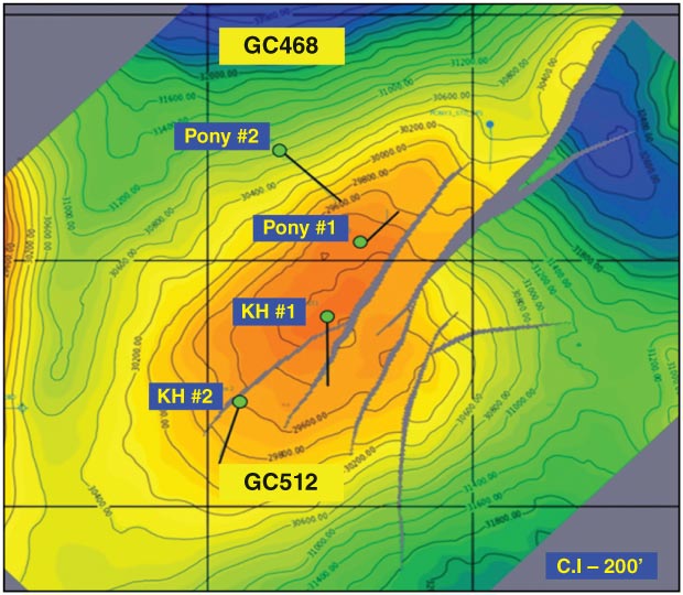
The Stampede Field is a four-way structural closure segmented by faults in Green Canyon blocks 468, 511 and 512. Figure 1 shows a legacy depth structure map of the main reservoir (the middle Miocene Gff40s) from wide-azimuth 3-D seismic data. It also denotes the discovery and appraisal wells. Note the absence of faults in the western flank of the structure.
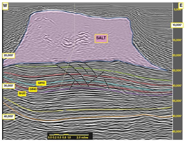
The structure formed as a four-way turtle in response to salt withdrawal from the basin. The evacuated salt formed an approximately 15,000 foot-thick canopy over the structure. Below the salt canopy is a 9,000 foot-thick section (from the base of salt to the base of the reservoir sands) that is composed of deepwater shale and turbidite sand packages in the upper/middle Miocene reservoir. As shown in the dual-coil seismic image in Figure 2, the three key pay intervals in the faulted, four-way structure are the middle Miocene (Serravallian) Gff10s, Gff40s and Sh20s.
FIGURE 2
Dual-Coil 3-D Image of Stampede Field (Gff10s, Gff40s and Sh20s Reservoir Zones)
Four wells with several sidetracks were drilled to discover and appraise the field, but none of the wells penetrated oil/water contact. Multiple fluid contacts were inferred from pressure data in the wells, implying that reservoir compartmentalization was difficult to support with faults mapped from existing seismic data.
The low-resolution seismic data (including both narrow- and wide-azimuth 3-D) also made it difficult to discern stratigraphic changes that could create flow barriers or compartmentalization. As a result, engineered faults from previous geological models were used to explain pressure differences between wells.
However, with the latest 3-D dual-coil seismic data, more small offset faults could be mapped, which helped explain some of the pressure differences observed. Fault seal analysis was performed to understand the flow barrier capability of faults, and this information was incorporated into the simulation model.
Filling the geological model with reservoir facies had its own challenges; the size and extent of the depositional fill and rock types in the fill were problematic. In addition, a process was needed to populate the geological model representing the fill, which also proved challenging.
The depositional setting for the reservoir pay zones varied from unconfined to weakly confined deepwater channel systems in a salt withdrawal basin. With the help of outcrop analogs, we interrogated seismic data to define the depositional environment boundaries. Despite several penetrations in the reservoir zones, there still was uncertainty in facies typing and fluid contacts. Consequently, core data, logs, fluid parameters and regional analogs were used as part of a multidisciplinary approach to reduce facies type and fluid contact uncertainties.
This process of integrating data and information from a variety of sources, tools and methods in the geological and flow simulation model greatly increased our understanding of the geology and petrophysics behind the workflow.
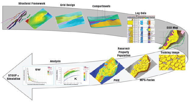
FIGURE 3
Multidisciplinary Workflow for Building the Simulation Model
Improved Trap Definition, Fault Seal
Figure 3 illustrates the multidisciplinary approach adopted to build the simulation model to address each of the key challenges involved in field development. Some of the key aspects of the work can be summarized as building the container (delineating trap and fault sealing), filling the container (resolving stratigraphic complexities), and filling the reservoir (reducing uncertainties related to compartmentalization and fluid contact).
As the flanks of Stampede Field’s four-way turtle structural trap subsided in response to salt withdrawal, crestal faults were created as a result of structural “flexuring.” The faults were both short and long, with some long enough to offset the base of the salt. To accurately estimate in-place resources and understand field compartmentalization, the structure’s shape had to be interpreted accurately and every possible fault had to be mapped correctly. In turn, structure shape and fault maps depend on acquiring a good seismic image.
Seismic image quality in subsalt environments generally is impacted adversely by the overlying salt geometry. In Stampede, while the center of the field was well-imaged, the flanks generally were not because of steep salt flanks, faulted base salt, intrasalt inclusions, etc. Previous seismic images, including WAZ data, were not clear enough to reliably map the flanks of the structure and identify small offset faults. Because of the low-frequency content (about 12 hertz) of the seismic data, the presence of subseismic faults could not be ruled out.
Both NAZ and WAZ seismic data were used in the exploration and appraisal phases, which involved limited subsurface illumination. As a result, while the central part of the trap was imaged relatively well, the peripheral part of the traps–especially in the north and northwest–were imaged poorly.
Dual-coil 3-D seismic data licensed during the field development phase showed an overall imaging improvement. We used dual-coil seismic and its derivative attributes to map the structural flanks more accurately and to delineate small offset faults that could be flow-baffles/barriers causing possible compartmentalization.
FIGURE 4
Current Depth Structure Map of Gff40s Reservoir Zone Using Dual-Coil 3-D Data
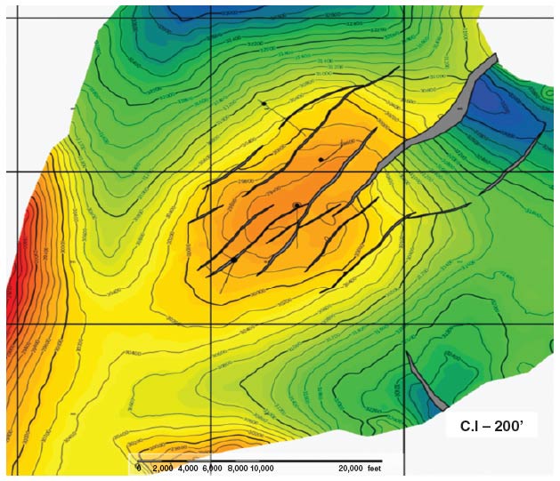
Figure 4 shows the current depth structure map of the Gff40s main reservoir zone using dual-coil seismic data. Compared with the legacy structure map in Figure 1, it shows new faults mapped on the northwest and central sections of the field. Discovery and appraisal well location and trajectories also are shown.
The ability of a fault to be a seal or flow barrier depends on various factors, including its extent, offset, lithology, and the nature of juxtaposition. Although several faults were mapped with dual-coil seismic, it also was necessary to perform a numerical modeling test to determine their ability to seal. Accordingly, 3-D multifault seal analysis was conducted for this purpose.
Structural maps, faults, and the geological model with lithology derived from drilled wells and extrapolated across the fields were input into the seal analysis. Fault properties such as throw distribution, shale gouge ratio (SGR), fault zone thickness, and fault zone permeability were calculated and analyzed.
The analysis indicated that faults with large local throws resulted in a low frequency of sand versus sand windows, faults with small local throws had minimal impact on cross-fault flow, and variations in cross-fault flow capacity changed along strike as the throw and related fault thickness changed. Keeping these mixed behaviors of the faults in mind, fault transmissibility multiplier (FTM) distributions were calculated for each fault and exported into the flow simulation model. This approach was a more realistic depiction of flow through faults than simple “seal” or “leak” fault categorizations.
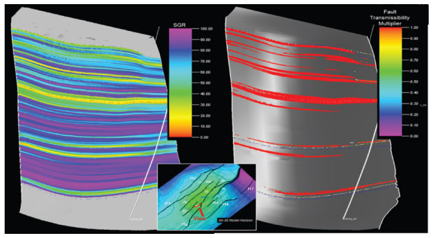
Figure 5 shows the SGR and FTM distributions for the fault shown in red in the inset map at bottom center. Displays are along the fault plane. High FTM values indicate flow across the fault.
FIGURE 5
Shale Gouge Ratio (Left) and Fault Transmissibility Multipliers (Right) For Fault Shown in Red in Inset Map (Bottom Center)
Fill And Facies Distribution
The three middle Miocene reservoir intervals (Sh20s, Gff40s and Gff10s) in Stampede consist of deepwater turbiditic sands. As noted, the basin started to develop in response to sediments coming in from the north and pushing the salt out to create space. There was a considerable clastic sediment input into the Stampede basin during the lower and middle Miocene period. The depositional environment for these sands changed from an unconfined channel setting in Sh20s to an increasingly confined channel setting in Gff10s as the basin itself became more confined with developing salt highs on the flanks.
Seismic data were used to determine the lateral extent of the reservoir intervals and their axial, off-axial, and marginal settings. However, the data did not have high enough resolution to determine the details of the facies distribution in the reservoir. To compensate, core data from the reservoir intervals and logs along with outcrop analogs from similar deepwater depositional settings were used to determine facies geometries and distribution.
FIGURE 6
Facies Population Approach for Gff40s Reservoir Zone
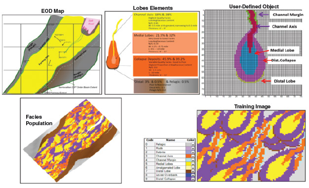
Figure 6 illustrates the multipoint statistics (MPS) facies population approach applied for each reservoir zone to build the geological model. The Gff40s zone is shown here, with the depositional environment scheme, facies elements, and their proportion used for object definition, training image and the final facies model. An object was defined with depositional facies elements (e.g., channel axis, median lobes, etc.), and a training image was constructed using that object. The training image was used to control the facies population in the 3-D geologic model.
Porosity was calculated from logs and calibrated by core data, and permeability was calculated using porosity/permeability transformation functions derived from core data. Facies population controlled porosity and permeability distribution in the geologic model.
Reservoir Compartmentalization
In addition to none of the Stampede exploration or appraisal wells penetrating OWC in any of the three reservoirs, a lack of pressure data from the “wet” zones in these intervals made estimating OWC more difficult. To compensate, we used log and core-based saturation data and modular dynamics tester pressures in a multidisciplinary tool, Geo2Flow, to identify reservoir compartments and free water levels (FWLs).
FWL estimation uses J-functions that couple porosity, permeability and saturations. Each well was fit separately to core-derived J-curves to come up with an FWL. Similar FWLs then were noted between the wells to determine possible compartments. The work suggested five compartments as a best estimate case in the Gff40s main reservoir.
FIGURE 7
Depth Structure Map of Gff40s Reservoir with Compartments And Estimated Oil/Water Contact Depths
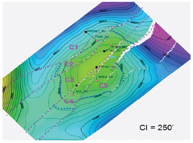
Figure 7 illustrates the outcome of the integration effort at the Stampede Field. It displays the updated depth structure map of the Gff40s reservoir with five compartments (identified by pink dashed lines) and their estimated OWC depths (blue dashed lines). Compartment C1 is an aquifer.
As part of the integration effort, geochemical analysis of fluids in the wells was incorporated to help better understand compartmentalization. Alkyl-benzene analyses for the reservoirs in the wells also supported the reservoir compartment and connectivity interpretation.
Integrating Higher-Order Details
Dual-coil seismic data enabled us to map new faults and extract higher-order reservoir details. A multifault seal analysis provided information on fault transmissibility, which was used dynamically in the flow simulation model. Integrating information from seismic with rock properties derived from logs, cores and outcrop analogs yielded a better understanding of variabilities in reservoir parameters and their portrayal in the geologic model. Tools such as Geo2Flow helped us combine rock and fluid properties to estimate fluid contacts.
All of these data and tools led to building a more realistic geologic simulation model and achieving a better understanding of the uncertainties associated with developing the Stampede Field. Based on the results of the simulation model, the field development plan could be finalized with the six producing and four injection wells as the base case.
The integrated workflow applied to optimize the development plan demonstrates that dual-coil seismic data can provide a better and more detailed picture of the subsurface, and that compartmentalization caused by faulting can be represented more realistically in the model through FTMs. An MPS approach is an ideal way to incorporate log, core and analog data into facies population.
In the absence of penetrated OWCs, the project showed that compartments and OWC estimates were better constrained by integrating pressure, water saturation and geochemistry data along with seismic interpretation.
Going forward, we intend to update the model with data every time we drill a development well. This should help refine the drilling and completion plans for future wells and optimize the performance of the Stampede Field.
Editor’s Note: The authors acknowledge WesternGeco for permission to use the seismic images in this article, as well as the contributions of subject matter experts on the Stampede project management team, and in the technology and excellence group at Hess.
 GOPAL MOHAPATRA is a geophysical adviser at Hess Corporation in Houston, where he is involved in generating exploration leads, maturing leads into drillable prospects, and drilling in the deepwater Gulf of Mexico. He is the lead geophysicist for the Stampede project looking after seismic processing, salt/velocity model building, seismic interpretation, and well planning and monitoring. Before joining Hess in 2007, Mohapatra served for 10 years at ExxonMobil as a deepwater exploration geophysicist in the Gulf of Mexico and Angola. He holds a B.S. and an M.S. in geoscience/geophysics from IIT Kharagpur, a Ph.D. in geophysics from the University of Arizona, and an M.B.A. in international finance from the University of Houston.
 ANDRY NABASIR is a geological adviser at Hess Corporation, focused on deepwater field development projects in the Gulf of Mexico. Before joining Hess in 2012, he served as a geological adviser at Chevron in the United States, Angola and Indonesia. He began his career in 1990 as a development/well-site geologist at PT Caltex Pacific Indonesia, and subsequently served the company as senior development geologist.
 STEVE STRAUSS is senior reservoir engineering adviser at Hess Corporation. He joined Hess in 2005 working on Bakken Shale and deepwater Gulf of Mexico development projects. After two years as senior operations engineer for conventional and unconventional plays at Vitruvian Exploration, Strauss returned to Hess in 2012. He began his career at Mobil, followed by Conoco, where he served for 21 years as an engineer and senior reservoir engineer. Strauss holds a B.S. in petroleum engineering from Texas A&M University.

Stampede Is Setting Gulf Of Mexico Records
How deep is the reservoir at Stampede Field?
Consider that the distance between the seafloor and the pay intervals exceeds the vertical height of Mount Everest, with the wells extending roughly 5.5 miles into the subsurface–including through 15,000 feet of salt. Given its extraordinary depth, Stampede is set to establish multiple Gulf of Mexico depth records when it commences production in 2018, including for the gas lift system to raise the produced oil to surface and the water injection system to maintain reservoir pressures.
The $6 billion project combines the Pony and Knotty Head discoveries into a single development. Knotty Head and Pony were discovered in 2005 and 2006, respectively. The two fields were conceived as stand-alone projects by their respective operators, but as 100 percent owner of Pony, Hess executed a joint operating agreement in 2012 with Nexen Petroleum and its partners on Knotty Head to merge the projects, with Hess appointed operator.
The front-end engineering and design for the project started in 2013, and the final investment decision was made in October 2014. Partners are Hess, Nexen, Unocal (Chevron) and Statoil, each holding a 25 percent working interest.
With a total depth of 34,189 feet, the Knotty Head No. 1 discovery well in Green Canyon Block 512 was the deepest well drilled at that time in the Gulf. It encountered approximately 600 feet of net oil pay. A sidetrack was drilled 4,500 feet to the south of the discovery well, reaching 32,986 feet TD and encountering 400 feet of net oil pay.
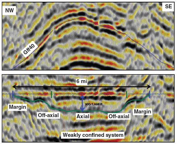
The dual-coil 3-D seismic section on top and its flattened version on bottom show the complex depositional environment of the Stampede Field’s main reservoir, the middle Miocene Gff40s. The fault-segmented, four-way structural closure was formed in response to salt withdrawal from the basin, with the evacuated salt creating a 2.5 mile-thick canopy over the structure.
The Pony No.1, drilled to 32,448 feet TD in Green Canyon 468, encountered 475 feet of oil-saturated sandstone. The Pony No. 1 sidetrack was drilled 2,700 feet northeast of the discovery well, reaching 30,634 feet TD and encountering 280 feet of pay. The Pony No. 2 appraisal, located 1.5 miles northwest of the No. 1 well, was drilled to 32,900 feet TD. It was followed by the No. 2 sidetrack 7,400 feet northwest of the discovery well, which was drilled to 33,362 feet TD.
Diamond Offshore Drilling’s Ocean BlackLion new-build drill ship began operations at Stampede late last year under a four-year contract with Hess, and the contractor’s Ocean BlackRhino is scheduled to enter service later this year at the field under a three-year contract.
The 10-well field development involves six subsea production wells and four water injection wells from two subsea drill centers. The wells will be tied back to the Stampede TLP with a designed topside weight of 11,500 tons. Modec International is providing the engineering, procurement, construction management, and commissioning services for the TLP.
The hull is being constructed in South Korea by Samsung Heavy Industries. Wood Group Mustang is performing the topsides engineering. The topsides are being built at Kiewit Offshore Services’ yard in Ingleside, Tx.
Other key contractors on the project include Intecsea, Proserv, Oceaneering, 2H Offshore, Subsea 7, and Vallourec. Enbridge is constructing and will operate an 18-inch, 16-mile pipeline lateral that originates at Green Canyon Block 468 to transport Stampede crude oil to a third-party system.
For other great articles about exploration, drilling, completions and production, subscribe to The American Oil & Gas Reporter and bookmark www.aogr.com.