


New Techniques Building Better Wells
By Chad Loesel, Azar Azizov, Lane Lemesany and Norwood Augustine
THE WOODLANDS, TX.–The methods used to plan, design and execute directionally drilled wells have evolved significantly to match the demanding conditions encountered in U.S. unconventional resource plays, leading to the introduction of multiple technologies that, in combination, have enabled reliable and improved wellbore construction.
These technologies include advanced PDC bits capable of drilling long tangents and laterals, improved bottom-hole assemblies with dynamic control systems, positive displacement motors (PDMs) with high-performance elastomers or precontoured power sections capable of delivering high power, and optimized motor geometry that provides a better compromise between delivering power and a consistent buildup rate (BUR) in the curve sections of horizontal wells.
However, maximizing well productivity and improving drilling efficiency remains a major challenge in drilling horizontal wells in unconventional plays. Reducing drilling times and eliminating trips for the curve BHA require a motor that can be rotated at high rpm in the vertical section while still achieving buildup rate in the curve.
New, steerable, optimized-design motor (ODM) technology with a short bit-to-bend (BTB) distance has achieved higher BURs in the curves than conventional motors at a lower adjustable kickoff (AKO) subangle.
Although the planned dogleg severities (DLS) remain at similar levels, drilling the vertical and curve sections of horizontal wells in the Niobrara Shale in the Denver-Julesburg Basin poses additional challenges, including:
- Rotating the BHA in the vertical section with a high AKO angle;
- Dealing with formation challenges;
- Holding the tool face to achieve consistent BUR in the curve; and
- Completing the vertical and curve sections in one run.
The latest generation of steerable motors with shorter BTB-distance designs has helped Anadarko Petroleum Corp. overcome these challenges in its Niobrara horizontal drilling operations. The new system has improved drilling performance significantly with excellent directional control.
With a goal of delivering a PDM capable of maximizing footage and ROP in the vertical sections while optimizing the performance and directional consistency in the build section, the latest-generation steerable motors (LGSMs) will improve performance and flexibility in two ways.
First, the reduced bend angle of the AKO, which is required to achieve directional objectives, increases tool performance and hole cleaning in the vertical section by providing increased surface RPM, compared with an ODM. Second, improved tool face control delivers more reliable BUR that helps maintain the same BUR capability from the kickoff point to the landing point, and minimizes the sliding time required to drill the curve.
Theory And Modeling
FIGURE 1
Three-Point Geometry Of Steerable Motor System
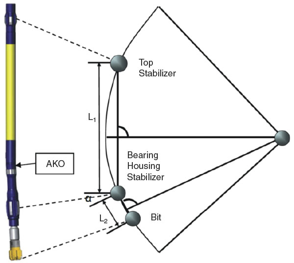
A steerable motor system with an AKO can be run in an oriented mode or in a rotary mode. In the oriented mode, the system produces a predetermined wellbore curvature. In general, this wellbore curvature is based on a three-point geometric model (Figure 1).
The three points of contact that determine the theoretical BUR capability of a steerable bent motor system are the bit gauge, a stabilizer located on the upper bearing housing, and a string stabilizer located on top of the motor. The distances from the midpoint of the string stabilizer to the midpoint of the upper bearing housing stabilizer, and from the bearing housing stabilizer to the bit gauge, define a reduced arc that establishes the theoretical BUR capability of the system.
The geometric model assumes that the bent motor, run in oriented mode, drills a smooth curve specified by the three defined contact points between the motor and the borehole wall. It considers only the three-point geometry of the system to make BUR calculations.
The theoretical value of the system’s BUR capability, as calculated by the geometric model, does not consider motor flexibility and bending effects, interaction between the bit and formation, formation dip, 3-D turning geometry, or bit characteristics such as bit type, gauge length, or gauge wear.
The calculated BUR capability of the system may be altered by adjusting any single component or a combination of the following:
- AKO angle;
- Blade outside diameter of the upper bearing and/or string stabilizer;
- Location of the top stabilizer in the BHA with respect to the bearing housing stabilizer, thereby altering one of the lengths that defines the three-point geometry; and
- Distance between the bit gauge and the bend point of the motor, thereby changing the other defining length of the three-point geometry.
The theoretical BUR capability of the motor could be calculated using the simple geometric model described above by adjusting the length between the bit gauge and the bearing housing stabilizer in the calculation. However, in the application planned for the LGSM, the operator needed the steerable motor assembly to be run slick. The uncertainty in the contact points between the BHA and the borehole wall for the slick motor necessitated another method to calculate the BUR capability of the LGSM.
A proprietary engineering software package was employed to calculate the BUR capability of the modified motor. The software analyzes the static and dynamic behavior of a complex drill string in a wellbore. The individual components of the drill string and BHA are broken into discrete elements. These elements then undergo finite-element analysis to determine the internal loads and borehole wall contact forces acting on the drill string and BHA for a specific wellbore profile and BHA design.
Using the resolved contact forces and loading, the modeling software predicts the BUR capability of the system. This provides a more complete and sophisticated analysis of BUR capability, compared with the geometric model.
Based on the modeling results, the steerable motor system was configured to achieve the BUR necessary to meet the operator’s drilling requirements at lower AKO angles. The approach used to achieve more consistent BUR was to further reduce the distance between the bit gauge and the bent housing of the motor. Hence, the resulting LGSM had a shorter BTB distance than the standard motor or ODM.
Niobrara Shale Case Study
The Niobrara formation consists of reservoir rock and source rock. The reservoir rock consists of four lateral chalk benches (Niobrara A, B and C, and the Fort Hays Limestone), and the source rock consists of three organic-rich interbedded shales.
Oil and natural gas are present at depths around 6,800 feet true vertical depth, with the three carbonate-rich chalk benches varying in thickness from 10 to 25 feet. Overall length of the Niobrara formation varies from 200 to 400 feet in the northeast portion of Colorado.
The Niobrara is a Cretaceous reservoir consisting of marine chalks and shales deposited in a deep marine environment.
In the typical casing profile of Niobrara horizontal wells:
- 9-5⁄8-inch casing is set below a freshwater interval.
- 8-3⁄4-inch vertical hole fluid is drilled to the kickoff point (the TVD of the KOP depends on the location of the well in the field).
- BUR required in the 8-3⁄4-inch curve interval is usually 10 degrees per 100 feet.
- The 6-1⁄8-inch lateral is drilled through the Niobrara or Codell, up to 9,000 feet in length.
Drilling Challenges
The major drilling challenges in a Niobrara well’s intermediate sections are:
- Extended time to complete the well as a result of tripping for curve assembly;
- Necessity for high penetration rates while drilling the 8-3⁄4-inch vertical section, which requires rotating the assembly from the surface at 60 rpm or greater;
- Keeping well trajectory as planned, utilizing a single 8-3⁄4-inch intermediate assembly;
- Difficulty achieving consistent BURs in the curve section; and
- Implementing a PDC bit that allows high ROP in the vertical section and maintains precise tool-face control in the curve section.
TABLE 1
These challenges led to a suboptimal drilling performance as a result of hidden nonproductive time such as extra trips for adjusting the motor AKO angle and reduced ROP while sliding.
Results
The modeling results led to reducing the planned AKO bend of the LGSM to 1.9 degrees for the intermediate 8-3⁄4-inch hole sections of the wells drilled in the Niobrara. This compares favorably with the 2.4-degree AKO bend of the standard motor and 2.1-degree AKO bend of the ODM. The planned BUR and AKO settings are listed in Table 1.
Despite the LGSM’s lower AKO angle setting for drilling the curve intervals of wells A and B, it not only showed similar or higher BUR, but also delivered more consistent BUR from the kickoff point to the landing point.
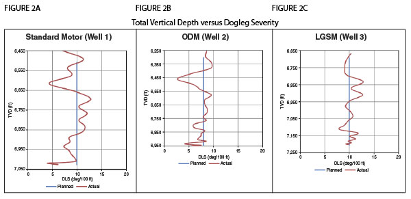
Three typical wells drilled utilizing these three motors were used for the comparison. The curve interval for well No. 1 was drilled using a 6-3⁄4-inch standard motor with a short, precontoured power section with a 2.4-degree AKO angle. Well No. 2 was drilled with a 6-3⁄4-inch ODM with a 2.1-degree AKO angle, while well No. 3 used a 6-3⁄4-inch LGSM with a 1.9-degree AKO angle.
The TVD versus DLS graphs are re-created in Figures 2A-2C. The red line shows the DLS in the well as a result of motor sliding and rotating, while the blue line represents the planned BUR. Large variations in DLS and inconsistency can be seen in both the standard motor and the ODM curves (Figures 2A and 2B). In contrast, the LGSM delivers constant and more predictable BUR from the kickoff point without large variations in the DLS (Figure 2C).
FIGURE 3
Curve Section Sliding Percentages
TABLE 2
TABLE 3
The following results are based on the analysis of the 16 Niobrara Shale wells drilled by Anadarko. The standard motor drilled the intermediate 8-3⁄4-inch sections in two runs (vertical and curve), while the ODM and LGSM drilled both the vertical and curve sections in one run. Comparing the curve sections shows similar sliding footage drilled by the three motors, with LGSM delivering the higher ROP while sliding with PDC bits (Figure 3).
Table 2 summarizes the results of the curve sections of the wells drilled. Eliminating one trip requirement compared with the standard motor led to one day saved when drilling with LGSM, while the higher ROP in the vertical and curve sections helped save more than half a day, compared with the ODM (Table 3).
Introducing the LGSM with a further-reduced BTB distance has improved drilling performance in Niobrara horizontal wells, delivering excellent directional control. The reduced bend angle of the AKO required to achieve directional objectives has increased tool performance and improved hole cleaning in the vertical section by providing increased surface rpm.
At the same time, improved tool face control has delivered more reliable BUR, helping to maintain the same BUR rate capability from the kickoff point down to the landing point, and minimizing the sliding time required to drill the curve.
CHAD LOESEL is a drilling engineer for Anadarko Petroleum Corporation, working in Denver, drilling horizontal wells in the Greater Wattenberg area. He also has drilled wells in the Granite Wash, Haynesville Shale, Permian Basin, Eagle Ford, and Uintah Basin. Previously, Loesel worked for Baker Oil Tools and Forest Oil Corporation. He earned a B.S. in petroleum engineering from Montana Tech University.
AZAR AZIZOV is product manager of drilling motors for Baker Hughes, based in Celle, Germany. He has served in various roles since joining Baker Hughes in 2000, beginning as a field engineer and moving through technical support and drilling engineering to applications engineering. He is an OASIS certified drilling applications engineer. Azizov earned a B.S. and M.S. in computer-aided control systems from Azerbaijan State Oil Academy. He is a member of the Society of Petroleum Engineers.
LANE LEMESANY is a drilling services account manager for Baker Hughes in Denver, where he sells directional drilling services to operators in North Dakota, Wyoming and Colorado. He began his career at Baker Hughes as a reliability engineer, doing failure analysis of downhole drilling tools for Western Hemisphere operations. He then moved to a U.S. land role, aiding in developing technology for drilling motors and locating cost-reduction opportunities. Lemesany earned a B.S. in mechanical engineering from the University of Texas at Austin.
NORWOOD AUGUSTINE is a drilling applications engineer at Baker Hughes, working with customers to develop the Powder River and Denver-Julesburg basins. He joined Baker Hughes as an MWD/LWD field service engineer in the U.S. Gulf Coast land region and Mexico. After three years, he relocated to Denver to work as a drilling applications engineer, focusing primarily on the DJ Basin. Augustine earned a B.S. in petroleum engineering from Louisiana State University.
For other great articles about exploration, drilling, completions and production, subscribe to The American Oil & Gas Reporter and bookmark www.aogr.com.