


Selecting the Right Technology is Vital in Horizontal Wells
By Jennifer Presley, Special Correspondent
Horizontal drilling and multistage hydraulic fracturing have unlocked vast quantities of natural gas in shale reservoirs. The lessons learned are being modified to achieve the same success in a rapidly expanding roster of unconventional tight oil plays, from the Wolfberry and Eagle Ford Shale in Texas to the Bakken Shale in North Dakota, the Mississippian Lime in Kansas and Oklahoma, and the Niobrara Shale in Colorado.
Independent operators are transitioning drilling and development programs from natural gas targets to those rich in liquids. A case in point is Chesapeake Energy Corp., which allocated half its 2011 drilling and completion expenditures to liquids-rich plays and forecasts that such plays will account for 85 percent of its 2012 drilling and completion expenditures.
“Liquids plays use the same horizontal drilling and multistage hydraulic fracturing methods that opened gas shale plays such as the Barnett, Fayetteville and Haynesville,” says George King, distinguished engineering adviser at Apache Corp., where he specializes in new technology and addressing problem wells. “In tight oil plays, drilling and fracturing technologies are evolving in a ‘fit for purpose’ way to capture the liquids reserves.”
As more and more horizontal wells are drilled and completed, operators are developing increasingly nuanced horizontal drilling and completion design strategies, while tackling the challenges of applying artificial lift in horizontal wells with systems and equipment that were designed for vertical wells, he says. “New requirements that limit well blow-downs will require lift systems to continuously unload the wells without releasing methane, increasing the need for and value of artificial lift systems that are effective in horizontal wells,” King says.
Horizontal Well Bore Challenges
When it comes to designing horizontal wells, oil and gas companies’ experience in shale gas plays has made it clear that formations can vary considerably from one play to the next and from well to well within the same play, making planning and knowledge critical tools. “No two shales are alike; they vary vertically and areally, especially along a well bore perpendicular to the frac direction. Operators must understand differences in shale fabric, in situ stresses, and geologic characteristics within each play, and how a formation will react to various drilling and stimulation designs that change in situ stresses,” King advises.
That makes geophysics, geology, petrophysics and rock physics vital to success in tight oil plays, he suggests. “There is a lot of laboratory work that can be done on the micro scale to study the fabric of the rock, but when you really get down to fracturing, you have to do it in the field and evaluate the specific behaviors you are generating,” King relates.
He adds that factors such as flow, pressure and the tectonics of the area all play roles in developing a successful fracturing job. “These are all factors that we routinely experience while monitoring a frac job. There are probably 20 things we can research as we go along from geological exploration to successful fracturing application,” King says. “That first fracturing job is going to be an experiment. After the data from the first job are analyzed and production data are received, that information is evaluated against 3-D seismic data to delineate a sweet spot within the reservoir that has the potential to be stimulated and completed in a favorable way.”
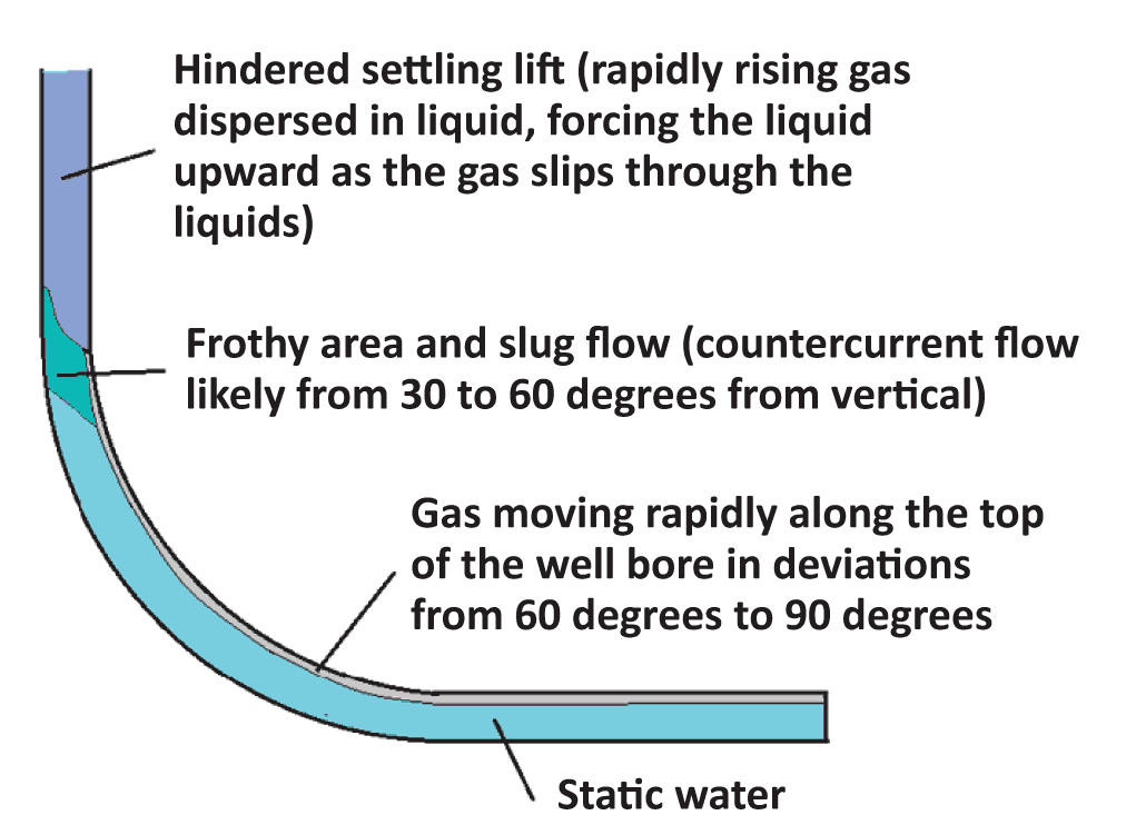
King adds that once drilled, stimulated and completed, all types of reservoirs have a certain degree of “natural lift,” or the tendency to flow of their own accord. The flow can be artesian in nature, he observes, where the reservoir pressure is higher than the pressure exerted by a full column of a single-phase well bore fluid, and the fluid flows to the surface if the flow path is unobstructed.
The other type of lift, hindered settling, is caused by gas bubbles rising rapidly and expanding as they get shallower and pressure decreases, King explains. He says the gas passing through the water will prevent it from settling quickly, and if the gas flow is high enough–above the critical gas flow velocity–it will force the water up the hole and out to the separators at some rate less than the gas velocity.
Of course, he notes, the goal of applying artificial lift systems such as electric submersible pumps, jet pumps, sucker rod pumps, progressing cavity pumps, chemical systems (foamers) and gas lift, in horizontal liquids-rich wells is to enhance the reservoir’s ability to flow at economic rates. “Applying artificial lift systems increases the ability of the liquids to flow to the surface, and by minimizing back pressure from the liquid rich column, assists in draining oil through fractures connected to parts of the reservoir outside the near-well-bore area to increase production and recover more reserves,” King says.
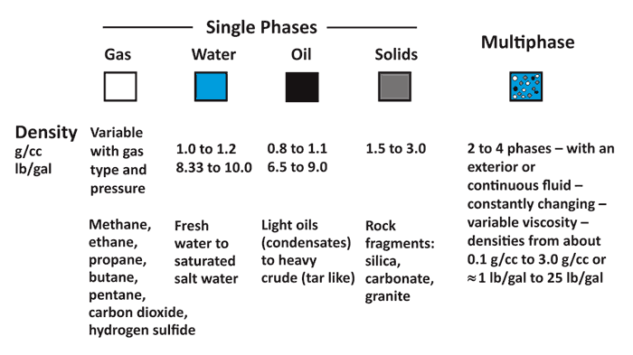
However, there are a number of complicating factors when it comes to applying artificial lift in horizontal wells. One is the obvious restriction to certain types of lift systems because of the well bores’ tight turns and long laterals, King mentions. Another, he says, is multiphase flow regimes. “It is common for a well to have a multiphase flow of liquids (both oil and water) as well as free and dissolved gases (Figure 1), especially in resource plays, such as the Eagle Ford, that have windows of predominately dry gas, wet gas and oil,” he observes. “It is not unusual at all to see wells in these plays that produce natural gas liquids, crude oil/condensate, and dry gas. This not only complicates the physics involved in artificial lift, but also makes some types of lift systems completely impractical.”
FIGURE 1
Multiphase Flow in Wells
Cleon Dunham, president of the Artificial Lift Research and Development Council, points out that another complicating factor is the steep decline rates typical of unconventional reservoirs. “Artificial lift must be considered up front when designing completions for liquids-rich plays because initial production rates can be very high, but they decline rapidly,” he states. “The artificial lift system must be flexible enough to handle the widely fluctuating production volumes.”
The kickoff point usually is thousands of feet below the surface, and the design of the build area and positioning of the lateral out to the toe can be key in implementing an appropriate artificial lift solution, according to Dunham. “The lateral section is designed to contact as much of the formation as possible. However, the profile of the lateral also impacts the type of artificial lift system that is most appropriate, as well as where it should be positioned in the well bore,” he says.
Dunham says three potential well bore profiles (Figure 2) commonly are used, with each presenting its own unique set of challenges. The toe-up profile provides a single liquid accumulation spot at the heel of the lateral near the kickoff point. “In this type of design, the well does not stay perfectly horizontal, but actually rises a bit as it goes along the formation path,” Dunham observes.
FIGURE 2
Well Bore Design Profiles
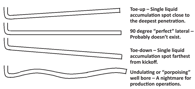
The toe-down profile provides a single liquid accumulation spot at the toe, farthest away from the kickoff point. This type of profile creates a “sump” that collects the liquids at the end of the lateral. Because artificial lift systems have difficulty moving liquids through a 5,000-8,000 foot lateral and up the vertical section, King says the toe-up design, with the low point of the lateral positioned in the heel and the horizontal section angled upward at 92-95 degrees as it extends into the formation, is emerging as the preferred option.
The third lateral design, the “undulating” profile, where the well bore is a series of peaks and valleys, is a “nightmare for production operations,” according to King.
Dunham agrees. “The multiple high and low points create a big problem because they allow for spaces where liquid can accumulate in the lateral, which means it will not produce a steady flow. This creates slugging, which can be a major problem from an artificial lift standpoint because it is very difficult for most systems to handle production without a steady input of liquid or gas.”
FIGURE 3
Artificial Lift Options
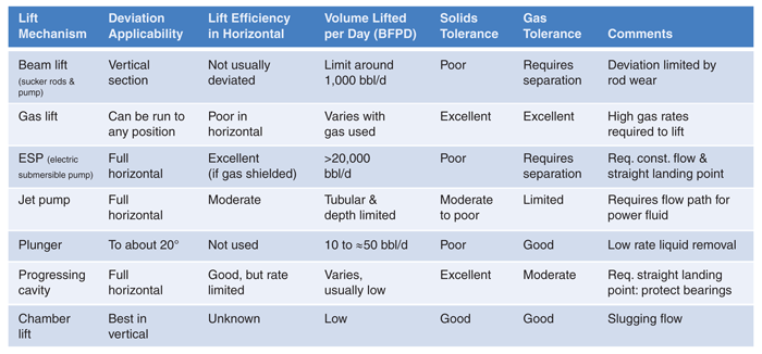
Artificial Lift Options
There are a variety of artificial lift systems that can be used in liquids production (Figure 3). Each system brings its own set of challenges when applied to horizontal wells, in part because of the deviation angle of the well (Figure 4).
FIGURE 4
Deviation Limits on Lift Systems
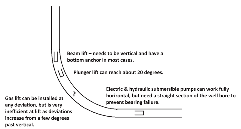
FIGURE 5
Back Pressure and Beam Lift Systems
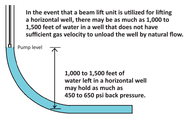
While beam pumping may be the most efficient method, it is also the most susceptible to gas locking in highly deviated wells, King says. “Beam pumps are used in a majority of the United States’ onshore wells, but they were developed for vertical wells,” he points out. “In the deviated section of a horizontal well, the rods slide against the tubing and may erode it unless rod guides are used to keep the rods from contacting the tubing wall. In addition to rod wear and gas locking, they also can experience the effects of back pressure (Figure 5).”
Dunham says rod wear is a reason beam pumps are not used more frequently in deviated wells. “If I have a rod string going through the deviated part of the well all the way to the surface, I have drag forces and erosion of the rods and tubing that have to be dealt with. That adds costs that can be avoided with different approaches.”
Like beam pumping, gas lift is used widely in vertical wells, but faces challenges in horizontal wells. “The biggest challenge is getting the gas lift equipment in place,” Dunham says. “Normally, gas lift equipment is installed with wireline tools, which only work to a deviation angle between 65 and 75 degrees from vertical. Putting the gas lift equipment in the highly deviated or horizontal part of the well requires coiled tubing or other special tools.”
Dunham says installing gas lift equipment in those sections of the well can be worthwhile if the lateral undulates. “Liquids and solids can collect in the low parts of an undulating lateral and hit the vertical section in large slugs, which can make it difficult to produce the well,” he says. “If the gas lift equipment goes out to the horizontal and the operator injects enough gas, it can move the liquid and solids along before they have the chance to collect, eliminating the slugs.”
King says gas lift has many limitations in deviated wells. “Gas lift only turns about 18 percent of the energy it consumes into lift,” he assesses. “That is efficient offshore, where you only need a little help to get the production moving, and where solids in the flowing fluid are a factor. Onshore, the gas rises to the horizontal lateral’s ceiling and stays there until it approaches the vertical section. Until that happens, the gas does not help lift the production (Figure 6). This is frustrating, but there is not much that can be done to make gas lift better.
FIGURE 6
Gas Lift Challenges
“What operators are looking for is a lift system that will work in a fully horizontal well and remain cost-effective, even in areas with high energy costs, which are a major slice of the overall expenditure for artificial lift,” King says. “There are some promising new solutions, but field trials will take a while to yield a usable system.”
ESPs
Electric submersible pumps are a viable option for producing large volumes of liquid. “If a well has a straight area long enough to hold the ESP itself, the motor and the associated equipment–30-40 feet–producers can land the pump there and get good results,” Dunham says. “ESPs need that straight area because flexing the drive shaft on the motor or the pump will cause the bearings to fail.”
High gas-to-liquid ratios can be problematic and cause ESPs to gas lock, Dunham observes, adding that ESPs require a constant flow of liquid to prevent overheating.
King agrees that liquid-heavy production streams are vital. “If the reservoir has a lot of liquid, you can probably use an ESP in a fully horizontal well. But any time you are running a motor, you are creating heat,” he comments. “Without enough liquid to provide cooling, the natural heat from the reservoir can combine with the motor heat to burn out the motor, shortening the ESP’s run life.”
The bottom line, according to King, is that a successful ESP application in a horizontal well requires a straight section of the well bore to land the pump, a low gas-to-liquids ratio, effective gas shielding at the intake, and sufficient liquids flow over the motor to keep it cool. The final requirement means that ESP users must have instrumentation in place that can automatically shut down the motor to avoid pumping a well dry. “If an operator has the exact right conditions to run an ESP successfully, it is a very effective and efficient pump,” King assesses. “However, if an ESP burns up or has other problems, it will require a rig to pull it out and run it back, which can be expensive.”
Dunham adds one other factor for consideration: solids tolerance. “Like all pumps, ESPs do not like sand,” he says. “Considering the huge amounts of proppant placed in horizontal wells during the hydraulic fracturing process, a certain amount of proppant invariably will be swept from the fractures and into the production stream over time. That reality can make ESPs less desirable than systems with a higher sand tolerance.”
Other Pumps
Progressing cavity pumps are less susceptible than ESPs to sand and other solids, but their application envelope has its share of limitations, according to Dunham. “PCPs can work at any deviation angle, but they do not work well in hotter downhole environments,” he details.
Like ESPs, PCPs handle dry operation or gas production poorly, and must be set in a straight section of the well bore to prevent bearing failure, King adds.
Jet pumps are another option for operators, King says. They can be used at any deviation angle through the full length of a horizontal well, but are less efficient than ESPs and have limited tolerance to solids and gases. They also require a dedicated flow path for the power fluid, he notes.
“All these options involve trade-offs in horizontal wells,” Dunham observes. “To use artificial lift effectively in horizontal wells, operators will need to look at each well’s characteristics–from their deviation and lateral profile to production stream variability and downhole temperatures and pressures–to determine which approaches will be effective and reliable.”
Editor’s Note: For additional information on selecting artificial lift systems for liquids-rich horizontal wells, consult the gas well deliquification section of the Artificial Lift Research and Development Council’s recommended practices.
For other great articles about exploration, drilling, completions and production, subscribe to The American Oil & Gas Reporter and bookmark www.aogr.com.