


Vapor Recovery
Strategies Optimize Vapor Control on Production Sites
By Ray McKaskle and Kevin Fisher
Editor’s Note: The following article is the second in a two-part feature on vapor control and recovery in oil and gas production operations. Part I appeared in AOGR’s August issue. Click the link to access in full the digital replica of that article.
BUDA, TX.–Controlling volatile organic compound (VOC) vapors generated in oil and gas production operations is becoming increasingly critical for safety, environmental, and economic reasons. Flares are the most common type of control equipment at production sites, and a flare-only control approach is the simplest vapor control option. However, a large field can require thousands of flares, and flaring becomes less economical with increasing production rates, since valuable rich hydrocarbon vapors are not recovered.
In addition to economic and operating considerations, environmental regulations also constrain the use of flares. Regulators typically assume 98 percent VOC destruction with flares, but even assuming that only 2 percent of the VOC is emitted at high production sites can bump the sites up against permit limits. All other things being equal, it is generally preferable to use a vapor recovery unit (VRU) to recover hydrocarbon vapors as a revenue-generating product than to oxidize vapors in a flare, which offers no opportunity to capture revenue to offset the costs of vapor control.
The trick, of course, is to integrate the operation of compressor-based VRUs and associated equipment into the site with low enough capital and operating costs and sufficient reliability such that the revenue from the recovered vapors justifies the additional expenditures. Operations including a VRU will invariably be more complex than a site that uses only flares for vapor control. The design must be such that operations staff can tolerate the requirements to support the additional equipment. Operators have leveraged a number of strategies to achieve these objectives.
While incorporating a VRU into the vapor control strategy can reduce the overall site emissions, it can be quite challenging to integrate VRU systems into upstream oil and gas production sites with satisfactory results from both economic and operational standpoints. A VRU and related equipment is more capital intensive than a flare, and maintenance costs and equipment downtime are usually higher. Moreover, as noted in Part I of this article, water and hydrocarbon condensation can create operational issues and lead to equipment damage. Oxygen contamination in the sales gas can be an issue when VRUs collect vapors from atmospheric-pressure storage tanks. Finally, revenue recognition for the oil and gas producer and allocation to royalty owners can be complicated.
Despite the challenges, however, VRUs can be part of an effective vapor control solution in these applications.
VRU Configurations
There are several ways that a VRU system can be configured within a location. The VRU can treat all the vapors formed at the site from the storage tanks with near-atmospheric pressure suction conditions. However, a large and expensive VRU can be needed for 100 percent capture using this approach. Furthermore, a gas blanketing system, catalytic oxidation unit, or other approach may be needed to prevent air from entering the storage tanks and creating issues with meeting the sales gas specification for oxygen.
FIGURE 1
Process Flow Diagram for Site with Surge Bottle
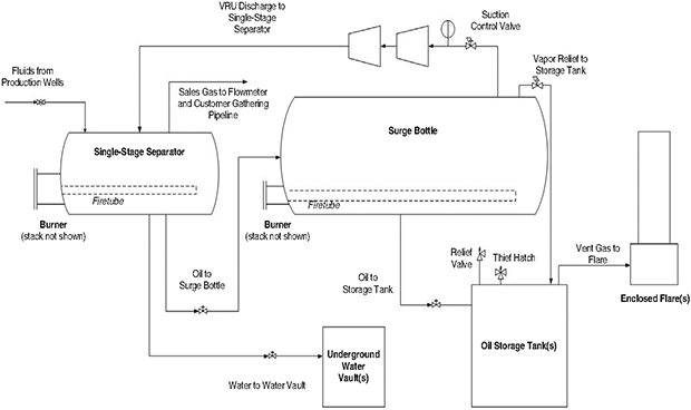
The VRU can take gas only from an intermediate pressure source such as the low stage of a two-stage separator, a surge bottle, or a vapor recovery tower (VRT). In these cases, one or more flares can then be used to control the vapor formed in storage tanks. This approach has the advantage of having flares as backup control devices in instances when the VRU is temporarily out of service. Figure 1 shows a process flow diagram with a surge bottle between the separator and storage tanks. The surge bottle feeds a VRU and a flare treats the vapors from the storage tanks. The arrangement is similar if the VRU is fed from the low-pressure separator in a two-stage separator or from a VRT.
In most cases, the gas compressed in the VRU is returned to the highest pressure stage of the separator, where it combines with the sales gas. An exception would be if there are local requirements that can consume the gas recovered by the VRU at a pressure lower than the pipeline. These might include feed to lift gas compressors or local fuel use, although the gas recovered by the VRU is typically more valuable on a heating value basis and the rich gas may not burn well in engines designed to run on much leaner natural gas.
Not much can be done about the fact that a VRU costs more than a flare in production applications. Flares are essentially passive equipment with very few moving parts. On the other hand, VRUs are engine or electric motor-driven, oil-lubricated compressor systems that have many moving parts. It is also more of a challenge for a VRU to handle the on/off and variable loads at these sites. However, there are ways to increase the throughput/capacity and reliability of the VRU to make operation of more expensive control equipment more economical in upstream oil and gas production.
Increasing suction pressure using surge bottles, intermediate pressure separators, and VRTs (to a lesser extent) can increase a VRU’s throughput capacity. Some operators also use another heater treater like a three-phase production separator to act as a surge bottle. Several types of compressors are being used in vapor recovery applications: reciprocating compressors, rotary screw compressors, rotary sliding vane compressors, and scroll compressors. The selection of compressor type is very important and should be given careful consideration when specifying or selecting a compressor for a VRU system.
Some VRU systems use high pressure gas as a motive force instead of a fuel-burning engine. These include eductor and booster compressor systems. However, their usefulness in production applications is limited because the highest pressure gas onsite is usually the sales gas and using some of this gas to drive this kind of VRU results in an intermediate pressure gas stream that lacks the pressure needed to get into the sales pipeline. This results in a need for more compression equipment to get the drive gas and/or recovered gas into the pipeline unless there is an onsite requirement that can always consume all the intermediate pressure gas.
Common Drawbacks
Regardless of the compressor type, a commonly noted drawback in this service is oil thinning. Rich gas compression, particularly in cold weather, can result in some water or hydrocarbon species condensing into a liquid phase that mixes with the compressor lubricating oil. Over time, oil thinning can lead to significant damage to the VRU compressor, such as bearing failures. The oil thinning problem is exacerbated by the start/stop nature of this application, as gases trapped in the VRU system cool after the VRU cycles off.
A two-stage reciprocating compressor that has been used for vapor recovery on more than 100 production sites was modified several times to address this issue. First, the interstage cooler was disabled and then some sales gas was blended in at Stage 1 discharge/Stage 2 suction to try to keep the gas from getting too rich in order to keep all hydrocarbon species in the vapor state. Insulation on suction and discharge lines is recommended as are adjustable enclosures, which can retain heat in cold weather and be opened to provide avenues for cooling in hot weather.
Adjustable timed warm-up cycles can give the VRU a minute or two to warm up before it needs to be ready to process gas. These can be actuated by a pressure transmitter that detects a slight increase in pressure in the source of the suction gas. A similar cool down or purge for a minute or two after the cycle is completed also can help, provided that the compressor can be run at this unloaded condition.
Using a VRU can sometimes result in some headaches with royalty payments to mineral rights owners as it can be a bit complicated to allocate the revenues generated by the VRU to a particular well, particularly when the VRU serves multiple separators or other vessels that can process feed from multiple wells at the same time. Oil and gas producers also may want to offset operating and maintenance costs for VRU systems against the revenue generated by the VRU, which adds another step in the process of allocating net royalties to mineral rights owners.
An additional complication that can be overlooked is that the gas recovered by the VRU typically has a much higher heating value than the sales gas, but it can be difficult to generate additional revenue based on the higher heating value. A grab sample to determine the composition of the sales gas is typically measured only on an intermittent basis. Samples are often taken when the VRU is not running, so in essence, the vapors recovered by the VRU are treated as having the same heating value as the sales gas.
A separate meter and separate sampling can be done for the gas recovered by the VRU, but this complicates coordination with the sales gas meter and composition. Flow-weighted sampling using a composite sampler can resolve these issues where the production rate is sufficient to justify the expense of using a composite sampler. Gases recovered by the VRU are proportional to the oil production, so this is one option for allocating revenues from recovered gases.
Peak Management Strategies
With some wells generating peak vapor flow rates as high as 30 times the daily average, there is a clear incentive to reduce the peak gas flow rate to reduce the capacity requirements for vapor control equipment. Producers are using several peak management strategies, including slug catchers, surge bottles/buffer tanks, and VRTs.
Slug catchers are simple devices that operate more or less as a “wide spot in the line.” In production operations, slug catchers need to be sized to handle the entire volume of liquid produced without the liquid level reaching the gas outlet before the production cycle ends. A larger size requirement for higher production rates increases the cost of the slug catcher more than other options because the vessel must be rated for the maximum pressure upstream of the choke. A flange also is required for access and cleaning. Also, there is no means of heating the slug catcher to prevent paraffin accumulation or liquids freezing.
Installing a surge bottle downstream of a one-or two-stage separator brings key advantages for peak vapor reduction. As mentioned, some operators also use another heater treater like a three-phase production separator to act as a surge bottle since heating is useful in preventing paraffin buildup and liquids freezing. Adding an extra stage of pressure drop reduces the overall amount of flash gas and some of it becomes available at an intermediate pressure that is easier to recover with a VRU while the amount of atmospheric pressure flash gas that needs to be controlled from the storage tanks is reduced (this intermediate pressure flash gas is much richer than the sales gas).
FIGURE 2
Surge Bottle Controls Schematic
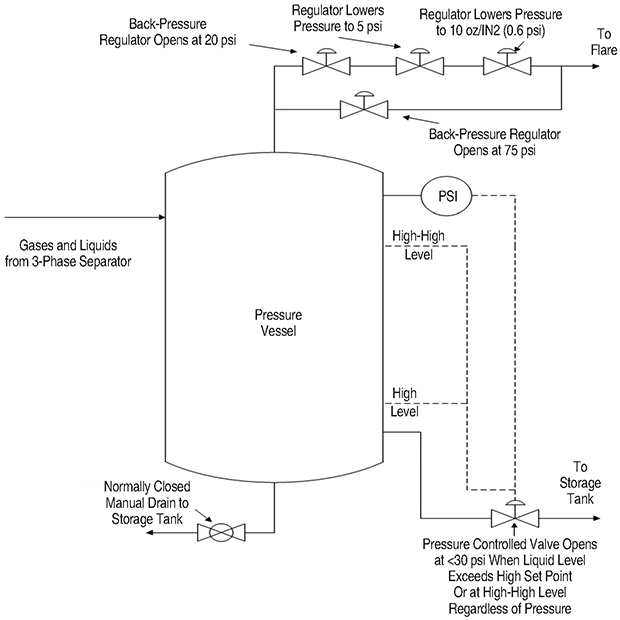
Figure 2 shows an early version of a surge bottle concept and related control functions developed for one operator’s production sites that became a part of the standard equipment setup for many of the company’s wells. As liquids flash into the surge bottle, the pressure builds and when it reaches a high set point, vapor exits the surge bottle and goes to a VRU or to a storage tank and then a flare. This reduces the pressure in the surge bottle.
If the pressure in the surge bottle reaches a high-high set point, vapors are vented from the surge bottle regardless of other conditions. Once the control device lowers the pressure in the surge bottle to a predetermined set point, the drain valve opens for oil at a reduced pressure to drain to the storage tank. However, it is important that the pressure that remains in the surge bottle is sufficient to move the oil to the storage tank. If the oil level reaches a high-high set point, the oil drains to the storage tank regardless of other conditions in the surge bottle.
The control philosophy evolved over the course of the surge bottle’s development. For example, a higher pressure to vent gas from the surge bottle set point was used on systems where this gas fed a VRU to increase the capacity of the VRU, and a gas regulator was added on a vapor line from the separator to the surge bottle to keep a minimum pressure in the surge bottle and ensure oil would drain to the storage tank. Sites with electricity can use a pump to move the oil from the surge bottle to the storage tank at lower operating pressures in the surge bottle.
A key lesson learned early on is that the surge bottle had to hold all the oil produced in one cycle before getting so full that oil had to be drained to the storage tank before the vapor control device had time to reduce the pressure in the surge bottle. If not, oil drained to the storage tank when the oil level reached a safe upper limit in the surge bottle regardless of pressure, which resulted in a high vapor generation rate in the storage tanks. Similarly, gas would vent if the pressure increased to the safe upper limit. These events often resulted in exceeding the capacity of the control device and some gas venting occurred.
Both experiences reinforced the concept that the best benefits of using the surge bottle came when it had the capacity to contain the entire slug of produced oil. This, coupled with increasing peak production rates, led to larger surge bottles as the concept evolved. Ten, three-foot diameter by eight-foot vertical vessels were put through a test campaign. At about half of the test sites, paraffin issues and cold weather freeze-ups were encountered. This led to changing the built-for-purpose vessel to a horizontal configuration to accommodate a fire tube for heating and to lower the vessel’s profile. The diameter was increased to six feet and the length was increased to 20 feet.
As peak oil production rates at individual sites trended up over the years as a result of horizontal drilling and improved fracturing techniques, the surge bottle-to-VRU and storage tank-to-flare became one of two preferred approaches. The other preferred approach swapped a VRT for the surge bottle.
Vapor Recovery Towers
FIGURE 3
Vapor Recovery Tower
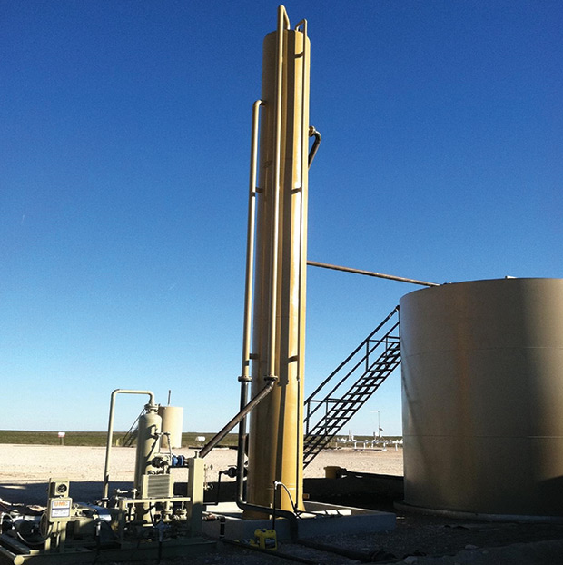
Photo courtesy of Reset Energy
A VRT is usually installed between the separator and the storage tanks in a similar arrangement to a surge bottle. Oil dumps from the separator to the VRT and then from the VRT to storage tanks. As shown in Figure 3, a VRT for an oil and gas production site is a small-diameter vertical vessel that is 35-40 feet tall. It operates at very low pressure at the top of the tower (on the order of 3 psig).
The height of the liquid level in the VRT provides a hydrostatic head for moving the oil to the storage tank. Since the oil in the VRT is at very low pressure, there is a minimal amount of flash gas formed when the oil goes to the storage tank. This is an operational advantage that the VRT has over a surge bottle as a lower flare capacity is needed for the storage tank vapors generated when oil goes from the VRT to the storage tank. Controls for the VRT are also generally a lot simpler than the surge bottle.
The low pressure in the VRT, coupled with the residence time in the VRT, allows most of the light ends to evolve as vapor and go to the VRU or other control device. One disadvantage compared to a surge bottle is the lower suction pressure that the VRT provides to the VRU. This requires a VRU with larger volumetric capacity (all other things being equal). Furthermore, because of the lower operating pressure in the VRT, it cannot reduce the peak vapor formation rate as much as a surge bottle. Oil dumps from the upstream separator to the VRT at its normal rate and flash gas is formed at peak rates similar to those of a separator dumping directly to a storage tank.
The geometry of the VRT does not lend itself well to heat input and issues with paraffins, plugging, and freezing have been encountered. VRT systems are typically designed for a 30-minute residence time, which can increase to 60 or 90 minutes as production declines. The increased residence time exacerbates paraffin, plugging, and freezing issues, and therefore, some operators take some VRTs at a site out of service as production declines. The VRT also needs to be tall enough to ensure the oil will drain to storage tanks under all conditions. This adds to the height profile of the site, which can be a concern in some installations.
Clearly there are some tradeoffs between the surge bottle and VRT concepts, but the arrangement of vapor control centered on a VRT feeding a VRU is used at hundreds of production sites.
All of these vapor control approaches continue to evolve. Some operators are combining multiple approaches, such as using a surge bottle feeding a VRT and even sending storage tank vapors to a VRU instead of a flare, nearly eliminating VOC emissions from flash gas. Mechanical refrigeration units can be used to recover some rich flash gas as NGLs in some locations, and sites with electricity and higher production rates make advanced control approaches more feasible. By considering all the site-specific factors, oil and gas producers can select an optimal strategy that best suits their objectives for production operations, vapor control, and regulatory compliance.
RAY MCKASKLE is a principal engineer at Trimeric Corporation in Buda, Tx. With 27 years of industry experience, he joined Trimeric in 2005 after serving as a senior field process engineer at Novellus Systems and as a staff engineer at Radian International. McKaskle holds a B.S. in chemical engineering from Oklahoma State University.
KEVIN FISHER is vice president at Trimeric Corporation. Before joining the company in 2003, he was a principal engineer at CrystaTech, a senior engineer at Radian International, and a chemical engineer at JFW Development. Fisher holds a B.S. in chemistry from Sam Houston State, a B.S. in chemical engineering from Texas A&M University, and an M.S. in chemical engineering from the University of Texas at Austin.
For other great articles about exploration, drilling, completions and production, subscribe to The American Oil & Gas Reporter and bookmark www.aogr.com.