


Project Models Interactions Between Parent-Child Wells In Anadarko Basin STACK Play
By Dave Ratcliff, Mark McClure, Garrett Fowler, Brendan Elliott and Austin Qualls
OKLAHOMA CITY–Operators are drilling and completing increasing numbers of infill wells in the proximity of existing producing parent wells, causing fracture driven interactions (FDIs) that often have negative impacts on both parent and child well production.
Impacts are highly variable between different plays, and the severity of the impact depends on factors such as well spacing and the parent well’s age.
Several techniques have been applied to mitigate impacts from parent/child well interactions, including preloading the parent well by injecting into it prior to the offset frac, varying well spacing and fracture sequencing, cube (or tank) development, chemical treatments, refracturing, and far-field diverters. While companies have been successful with all these strategies, there is no single “silver bullet.” Each technique comes with different costs and benefits.
FDIs involve complex interactions of physical processes. Pressure depletion around the parent well reduces stress and causes propagation of the child fractures toward the depleted region. Asymmetric flow also may be driven by fluid diverting into pre-existing hydraulic fractures from the parent well. Asymmetry may be reduced or eliminated if the parent well is repressurized by preloading or inflow from FDIs. As fluid flows into the parent fracs, it may flow all the way into the parent well, carrying proppant and potentially causing damage and/or well blockage. Fluid can crossflow through the parent well, and then flow back out of the well from other locations along the lateral.
Of course, production also is impacted by production interference. After infill drilling, both the parent and child wells compete to produce fluid from overlapping volumes of rock.
Chemical and multiphase effects play a major role in some parent/child interactions. Because these effects are dependent on formation properties, they are highly variable by formation. FDI damage can be diagnosed from a large, persistent loss of production at the parent well (once physical damage mechanisms have been ruled out). The detailed mechanisms are usually not known in detail, so chemical mitigation treatments often have taken a “kitchen sink” approach by pumping surfactant, citric acid, aromatic solvents and iron chelators to attack a variety of types of damage.
STACK Pad
Devon Energy performed a comprehensive modeling study, delivered by ResFrac, that calibrated a coupled “true” hydraulic fracturing and reservoir simulator to a complex set of observations from a five-well pad in the STACK play in the Anadarko Basin. The model was constrained by sealed wellbore pressure monitoring, interference testing, pressure responses during FDIs, production data and responses to chemical treatment. It was possible to match the full set of observations in a single, continuous simulation by calibrating the fracture toughness and leak-off, the permeability and relative permeability, a parameter related to proppant transport, and parameters related to a “fracture conductivity damage” mechanism built into the simulator.
The fracture damage calculations mimic the reaction of frac fluid with the formation fluid as they mix in a hydraulic fracture during and after a frac hit. The interpretation of fracture conductivity damage is corroborated by production impacts after FDIs, positive response to chemical mitigation treatments and direct sampling of material from the wellbore. Because of the volume and quality of calibration data available, it is possible to constrain the key uncertainties of the model. It now can be used to design strategies to mitigate negative impacts from parent/child interactions.
The project targeted the upper and lower Meramec formation. Four offsetting child wells were drilled two years after the parent well was drilled in the drill spacing unit. In addition to the child wells, another well was included in model that was outside the DSU. This well was located on the opposite side of the parent and completed one year before the child wells in the DSU. Parent well production was significantly impaired following the stimulation of all four child wells. Based on work to remediate and restore the parent well’s production, evidence suggested chemical damage to proppant pack conductivity at least partially responsible for production impairment.
A modeling study was performed to investigate potential physical causes and mitigation strategies. The hydraulic fracturing and reservoir simulator used in the study is well suited to describe parent/child interactions because it fully couples crack propagation and transport with multiphase flow and production. It is possible to perform detailed FDI simulations. The model can simulate the displacement of frac fluid into a hydrocarbon-filled parent well fracture as it reopens during an FDI, neighboring fractures propagate and stress shadow one another, proppant remobilizes, and fluid crossflows through the well.
For this study, a simulation was constructed and calibrated to match a complex series of events with fracturing and production across multiple generations of wells. The simulator models FDI-related damage as a process that causes conductivity loss as damage material accumulates in response to interaction of frac fluid with the formation and hydrocarbons in the fracture. Because the details of the damage reactions are not known in detail, damage is modeled as a generic process. In addition, reduced fracture damage from injecting a chemical mitigation treatment is modeled.
Frac Sequencing
Figure 1 shows the well spacing and frac sequence across the pad for all five wells. All five wells were modeled in one continuous simulation that included all fracture injection sequences, offset frac hits, initial production responses, production responses from FDIs, production responses from chemical treatments and pressure interference testing.
FIGURE 1
Well Position and Frac Timing
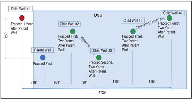
A sixth well (child No. 1) is just outside the DSU and was used only to simulate an FDI from an offset operator’s pad. Three stages were modeled in the parent well and two stages were modeled in each child well. Actual production was scaled down accordingly. All fractures and diagnostic data indicate that these fractures are planar in nature and were modeled as such.
One year after the parent was completed, child well No.1 was drilled and completed higher in the column relative the parent well. The parent experienced a severe FDI during the completion of this child well. To simplify the simulation, only the initial FDI from the first child well was modeled. To account for production interference between child No. 1 and the parent well, a no-flow boundary was activated halfway between both wells at the time that the child came on production.
Two years after the parent well was completed, the four child wells (nos. 2, 3, 5 and 6) were fractured. They were completed in pairs and each pair was zippered. The second pair was completed one month after the first pair.
Eight major observations characterize the interactions of the parent with the four child wells. These observations are drawn from data, including sealed wellbore data that had been correlated to fiber strain data from offset pads, pressure observations during frac operations, pressure interference testing during production, and actual production data.
Fracture Lengths
Fracture lengths were matched with fracture propagation rates using a method developed by Devon Energy that uses a sealed wellbore pressure with no perforations and filled with a low-compressibility fluid. As fractures cross the wellbore, deflections in the pressure can be observed. The timing of the pressure responses has been correlated to actual distributed strain sensor fiber measurements, confirming that they are caused by fracture intersections. By using sealed wellbores at different distances from the wells being fractured, both the lengths and propagation rates can be discerned. Within the model, fracture lengths and propagation rates are tuned using a combination of parameters, such as fracture toughness and pressure dependent permeability.
The model allows specification of an initial fracture toughness, and then a relative fracture toughness scaling parameter. The latter parameter allows fracture toughness to increase with the square root of fracture length or height (whichever is smaller). Greater toughness requires more fluid pressure to propagate fractures, and so they become shorter with larger apertures. Therefore, toughness is a key parameter in determining propagation velocity and total length.
Pressure-dependent permeability (PDP) describes the apparently increased leak-off associated with propagating fractures. It may be caused by multiple fracture strands propagating from a single cluster or the partial, temporary dilation of natural fractures at elevated pressure. In the model, this process was approximated by applying a reversible permeability multiplier as a function of pressure. The apparent permeability to leak-off is assumed to increase significantly as pressure begins to exceed the minimum horizontal stress (Shmin).
As the fracture area increases, the total fracture leak-off increases, which has the effect of slowing fracture propagation as time progresses and it grows larger. PDP is useful for modeling water flowback at the beginning of production. Without PDP, the fractures may close too slowly, and there can be a large mismatch between the actual and simulated water production.
FDI Intensity
The second key observation for calibration was the intensity and magnitude of an FDI observed on the parent well while fracturing the two closest offset child wells. Figure 2 shows that magnitude of each FDI from child well nos. 2 and 3 was small, generally less than 200 psi and often much smaller. In addition, it indicates that most DFIs were coming from the child well No. 2, which is the closest to the parent.
FIGURE 2
FDIs on Parent Well (Majority of Small-Magnitude FDIs from Child No. 2)
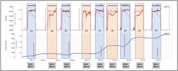
The modeled pressure in the parent increased while child nos. 2 and 3 were fracturing. Several FDIs were observed and correlated to individual fracture arrivals. Note that only child No. 2 initiated a frac hit on the parent. These FDIs were small, very similar to the actual data.
The preferred fracture growth of child No. 3 was away from the child No. 2, which was effectively shielding the parent from the child No. 3’s fracture growth (Figure 3). The fractures from the third child wanted to grow away from the higher-stressed area of child No. 2. Subsequently, child wells 5 and 6 also grew away from the parent well.
FIGURE 3
Child No. 2 Shielded Parent Well from Child No. 3 FDIs
Pressure interference testing revealed the amount of interwell communication at the start of production. All wells were shut in after fracturing. The first well to be put on production was child No. 2. The resulting change in pressure was noted in the offset wells that were still shut in. Child No. 3 was placed on production next, and so on. Figure 4 shows the well layout and the communication between each well. Except for child No. 2 not communicating with child No. 6, all wells had some level of communication.
FIGURE 4
Well Communication Across Pad
(All Wells Communicating Except Child Wells 2 and 6)
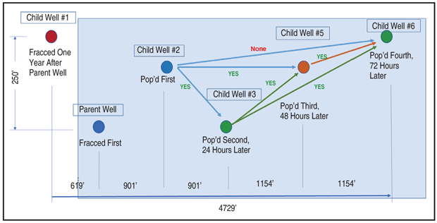
The exact pressure interference schedule was recreated in the model. For each well put on production, a line was placed to show a change in slope corresponding to a well being put on production. In each instance, the corresponding pressure change in the other wells was replicated.
The pressure interference results were replicated by the simulator by allowing proppant to “bridge” between wells. Proppant distribution in the model is calibrated by modifying parameters affecting proppant immobilization and fracture coalescence. Proppant immobilization represents the proppant that is immobilized or left behind due to kinks, ledges, etc., that may occur in the fractures. With lower proppant immobilization, proppant flows farther into the fracture, and can form a greater total propped area.
Pressure interference also was impacted by the simulator’s fracture collision logic employed. Fractures can connect with offset wells via two mechanisms: direction collision of fractures in between the wells, and collision of a fracture directly with an offset well. When a fracture intersects an offset well, it is assumed to connect into the nearest perforation cluster, if it is within a certain specified distance (assumed to be 10 feet in this study). Either way, once fractures connect between wells, proppant can transport along them, forming continuous flow pathways and causing interference.
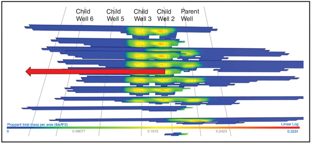
Figure 5 illustrates communicative pathways by showing the placement of proppant in each fracture. The hotter the color, the more proppant placed. Child wells 2 and 3 have a large amount of overlapping proppant, and the communication was very high (as indicated by a large slope change on the simulated pressure interference test). This matches the strong communication measured during the field test.
FIGURE 5
Proppant Bridging Between Wells
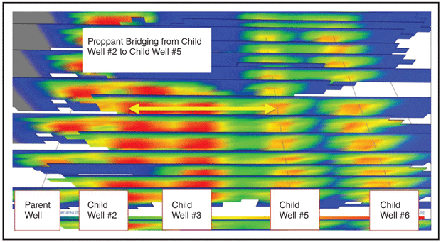
Communication exists for all other wells, but degrades as a function of distance because the proppant pathway is finite conductivity. The proppant pathway between child wells 2 and 6 was so distant that neither the simulator nor the actual data recorded any interference between them. There was a distinct gap between child wells 5 and 6, with only a small amount of bridging in only one fracture, thereby limiting communication between No. 6 and the other wells.
Editor’s Note: The preceding is the first in a two-part article on a comprehensive modeling study of complex parent-child well interactions in a five-well pad in the STACK play. Part II will appear in AOGR’s October issue and cover the model calibration to the remaining observations, model prediction and match historical production rates, and discussion of damage mitigation and remediation in the parent well.
DAVE RATCLIFF joined ResFrac in 2019 as the company’s first completions and reservoir engineer and its fifth employee. He has nearly 28 years of oil and gas experience in a variety of disciplines. Before joining ResFrac, Ratcliff spent 10 years working as a petrophysicist and petrophysics department manager for both Forest Oil and QEP Resources. Additionally, he spent 13 years with Schlumberger Wireline in various field, management and design roles. Ratcliff holds a B.S. in mechanical engineering from the University of Texas at Austin.
MARK MCCLURE is co-founder and chief executive officer of ResFrac. Before founding ResFrac in 2015, McClure was an assistant professor at the University of Texas at Austin in the department of petroleum and geosystems engineering. He serves on a number of scientific and academic boards and committees, and as an adjunct professor at Stanford University. McClure holds a B.S. in chemical engineering, an M.S. in petroleum engineering, and a Ph.D. in energy resources engineering from Stanford University.
GARRETT FOWLER is chief operating officer of ResFrac Corp. in Palo Alto, Ca. Prior to joining ResFrac as vice president of operations, Fowler was principal reservoir engineer at Tachyus Corp., where he worked with national oil companies, supermajors, and independents on deploying data science solutions. Before that, he was a reservoir engineer for Occidental Petroleum specializing in waterflood surveillance, piloting, and optimization. Fowler holds a B.S. in energy resources engineering and an M.S. in petroleum engineering from Stanford University.
BRENDAN ELLIOTT is a completions engineer in the drilling and completion technology group at Devon Energy. Primarily focused on complex development planning, modeling and fracture diagnostics, Elliott supports the Delaware Basin and Devon’s other major operated areas. Elliott has a B.S. from Texas A&M University, an M.S. in petroleum engineering from the University of Texas at Austin, and is currently a Ph.D. candidate in petroleum engineering at UT Austin.
AUSTIN QUALLS is a reservoir engineer in Devon Energy’s Delaware Basin business unit. At the time of the five-well STACK pad modeling study, he was working in the Anadarko Basin with a focus on future development planning in the STACK play. Qualls has a B.S. in petroleum engineering from the University of Oklahoma.
For other great articles about exploration, drilling, completions and production, subscribe to The American Oil & Gas Reporter and bookmark www.aogr.com.